
Module 1: Configure OTV
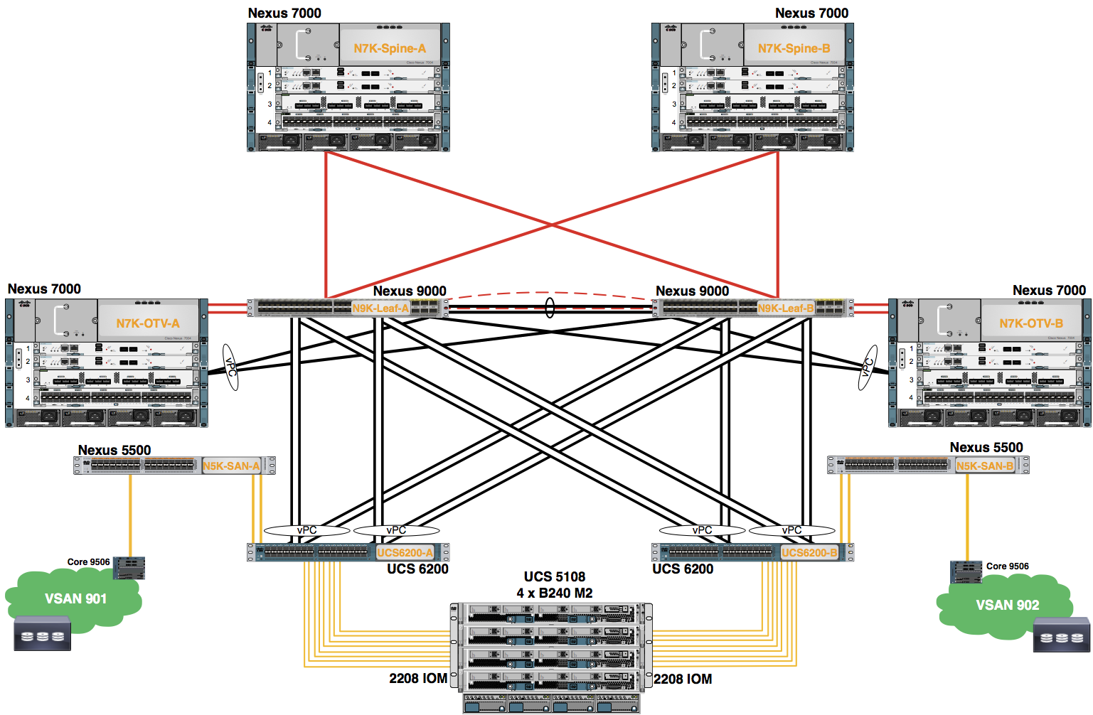
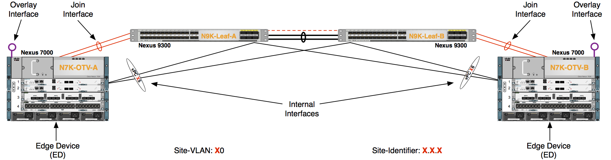
In this lab, you are going to configure Overlay Transport Virtualization (OTV) using a multicast enabled core for the control plane.
-
Enable the OTV feature in the OTV VDC.
POD-0-OTV-:
        #Config Block 1

        config
        feature otv
        end
-
Create the OTV Site-VLAN and extended VLANs.
POD-0-OTV-:
        #Config Block 2

        config
        vlan 000,11-12,21-22
-
Return to your Leaf switches to make Port-Channel 05 and 06 vPCs.
POD-0-Leaf-:
        #Config Block 3

        config
        interface port-channel 05
        vpc 05
        interface port-channel 06
        vpc 06
        exit
-
Return to your OTV VDC and configure the OTV Internal interface and allow the OTV Site-VLAN and OTV Extended-VLANs for Layer 2 connectivity.
POD-0-OTV-:
        #Config Block 4

        config
        interface port-channel 06
        switchport trunk allowed vlan 000,11-12,21-22
        no shut
        exit
-
Configure IGMP Version 3 on the OTV Join interface.
POD-0-OTV-:
        #Config Block 5

        config
        interface port-channel 100
        ip igmp version 3
        exit
-
Configure the OTV encapsulation to use the VXLAN-like IP/UDP header format.
POD-0-OTV-:
        #Config Block 6

        config
        otv encapsulation-format ip udp !Changes the default gre encap to udp encap
        exit
-
Configure the OTV Overlay interface.
POD-0-OTV-:
        #Config Block 7

        config
        otv site-vlan 000
        otv site-identifier 0.0.0
        # % Site Identifier mismatch between edge devices within the same site will prevent OTV local site adjacencies from coming up
        interface overlay 1
        otv join-interface port-channel 100
        # OTV needs join interfaces to be configured for IGMP version 3
        otv control-group 239.1.1.1
        otv data-group 232.1.1.0/24
        otv extend-vlan 11-12,21-22
        no shut
        exit