
Lab 3
Lab 3: Configure UCSM SAN
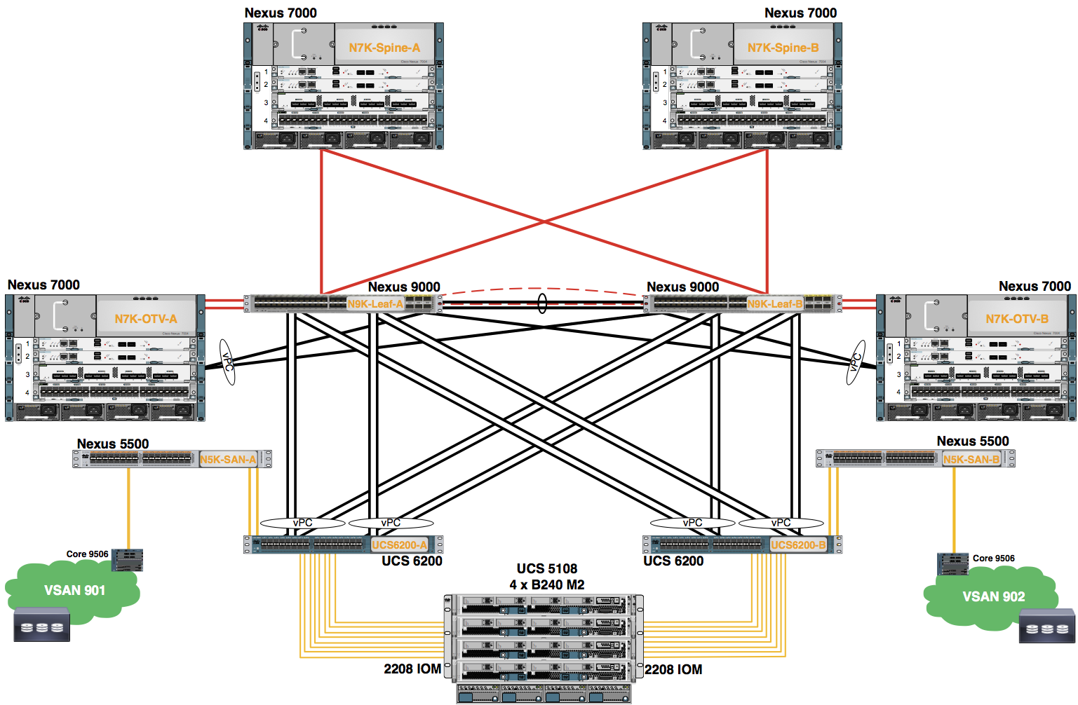
We are going to configure FCoE on the UCS to enable multi-hop FCoE through a pair of Nexus 5500 acting as SAN switches to a pair of MDS 9506s with 10 GB FCoE cards. The MDS’s are connected to a Netapp storage array that is providing the boot luns for the blade servers.
In this lab, you create the VSANs on the Fabric-Interconnects and configure the FCoE Uplinks as shown in the diagram below.
SAN Terminology
- Fibre Channel (FC) is a multi-gigabit-speed network technology primarily used for storage networking. FC is a serial data transfer architecture developed by a consortium of computer and mass storage device manufacturers and is the widely accepted protocol used for Storage Area Network (SAN)
- Fibre Channel Protocol (FCP) – FCP is the transport protocol (similar to TCP used in IP networks), which transports SCSI commands over Fibre Channel networks
- Fibre Channel over Ethernet (FCoE) – FCoE is an encapsulation of Fibre Channel frames over Ethernet networks. This allows Fibre Channel to use 10 Gigabit Ethernet networks while preserving the Fibre Channel protocol
- Fibre Channel Host – computer system (typically a server) that accesses a FC network by means of a FC interface card known as a Host Bus Adapter (HBA)
- SAN – a storage area network (SAN) is an architecture to attach remote computer storage devices to servers in such a way that the devices appear as locally attached to the operating system. Elements in the SAN include: Switches, Fabric, Connections, and Storage Devices (such as disk arrays, tape libraries, and optical jukeboxes)
- SAN Fabric – the hardware that connects workstations and servers to storage devices in a SAN is referred to as a "Fabric." The SAN Fabric enables any-server-to-any-storage device connectivity through the use of Fibre Channel switching technology
- SAN Switches – network switches compatible with the Fibre Channel (FC) protocol. SAN (or FC) switches allow the creation of a Fibre Channel Fabric that is currently the core component of most storage area networks
- Target – a storage resource used by servers connected to a SAN is known as a "target.” A target can be a disk, a disk array or other storage array
- N_Port – an N_Port is an end node port on the FC Fabric. This could be an HBA (Host Bus Adapter) in a server or a target port (Storage Processor) on a storage array
- F_Port – an F_Port is a port on an FC switch that is connected to an N_Port. The port into which a server’s HBA or a storage array’s target port is connected is an F_Port
- E_Port – an E_Port is a port on an FC switch that is connected to another FC switch. The connection between two E_Ports forms an Inter-Switch Link (ISL)
- NPV – N Port virtualization (NPV) is a FC solution designed to reduce switch management and overhead in larger SAN deployments. Switches operating in the NPV mode do not join a Fabric; rather, they pass traffic between NPV core switch links and end devices, which eliminates the domain IDs for these edge switches
- NPIV – N_Port ID Virtualization (NPIV) is an FC solution that allows multiple N_Port IDs to share a single physical N_Port. This allows multiple Fibre Channel initiators to occupy a single physical port, easing hardware requirements in SAN design, especially where virtual SANs are called for
- VSAN – a collection of ports from a set of connected Fibre Channel switches that form a virtual Fabric. Ports within a single switch can be partitioned into multiple VSANs, despite sharing hardware resources. Conversely, multiple switches can join a number of ports to form a single VSAN
- FLOGI – Fabric Login is an FC process where FC hosts or disks are allocated a Fibre Channel ID (FC_ID) from a directly-connected FC switch.
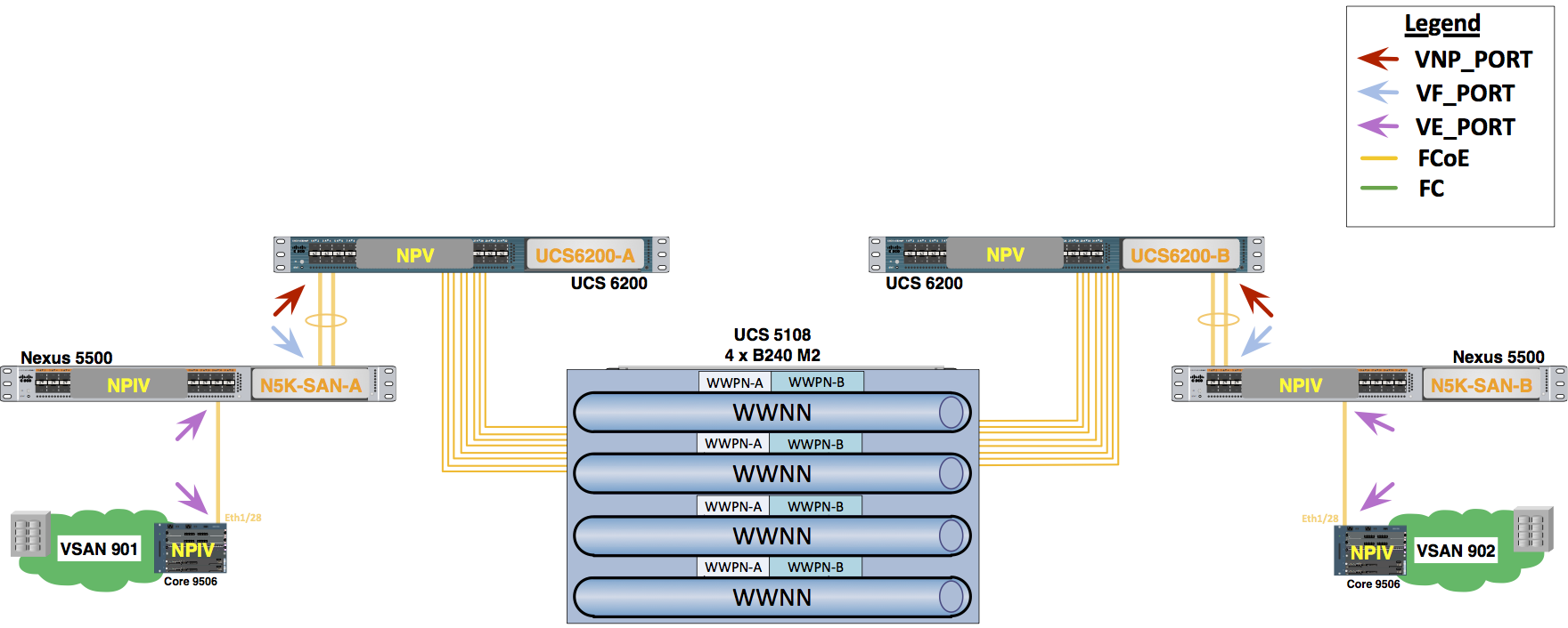
Note NPV and NPIV Modes on the UCS 6200 and MDS 9500/Nexus 5500 for this lab.
The UCS 6200 Fabric Interconnect switch operates in N-Port Virtualization (NPV) mode and not as a FC switch in the Fabric. The Fabric Interconnect joins the Fabric through a normal FLOGI and is issued N_Port IDs from the Nexus 5500 FLOGIs (Fibre Channel Fabric Logins) and zoning are also controlled by the Nexus 5500 when it is in NPIV mode, as in this lab. NPIV (N_Port ID Virtualization) mode for all VSANs allows access control, zoning, and port security to be implemented at the application level.
- World Wide Name (WWN) Address – 64-bit address that is used within the Fibre Channel specification for assigning a unique ID to each element within a Fibre Channel Fabric. WWNs are classified as WWPN and WWNN
- World Wide Port Name (WWPN) – unique address assigned to a port (vHBA) in a Fibre Channel Fabric. The WWPN performs a function equivalent to the MAC address in Ethernet protocol
- World Wide Node Name (WWNN) – unique address assigned to a node (UCS server blade) in a Fibre Channel Fabric. It is valid for the same WWNN to be seen on many different ports (different addresses) on the network, identifying the ports as multiple network interfaces of a single network node
- Virtual Host Bus Adapter (vHBA) – a virtual interface providing Fibre Channel over Ethernet (FCoE) from a server blade to a vSAN through a virtual interface on the 6200 Fabric Interconnect
FCoE Terminology
FCoE VLANs
FCoE packets must be exchanged in a VLAN. For FCFs with a Fibre Channel stack that includes multi-VSAN capabilities like the Cisco Nexus 5000 Series, the FCoE traffic belonging to different VSANs must remain separated by different VLANs on the Ethernet plane. This choice simplifies the implementation, since it removes the necessity to include both a VLAN and a VSAN header in each FCoE packet. The VLAN is assumed to be a proxy for a VSAN. For this reason, the Cisco Nexus 5000 Series software introduced the concept of a mapping table between FCoE VLANs and Fibre Channel VSANs. For each Fibre Channel VSAN used in the Fibre Channel fabric, the administrator associates one and only one unique FCoE VLAN. All FCoE packets, tagged with that VLAN ID, are then assumed to belong to the corresponding Fibre Channel VSAN. The Cisco Nexus 5000 Series implementation also expects all FCoE VLANs to be used exclusively for FCoE traffic and never shared by other traditional Ethernet payloads.
FIP
FCoE Initialization Protocol (FIP) is the FCoE control protocol responsible for establishing and maintaining Fibre Channel virtual links between pairs of FCoE devices (ENodes or FCFs). During the virtual link establishment phase, FIP first discovers FCoE VLANs and remote virtual FC interfaces. Then, it performs virtual link initialization functions (fabric login [FLOGI] and fabric discovery [FDISC], or exchange link parameters [ELP]) similar to their native Fibre Channel equivalents. After the virtual link is established, Fibre Channel payloads can be exchanged on the virtual link, and FIP remains in the background to perform virtual link maintenance functions. It continuously verifies reachability between the two virtual FC interfaces on the Ethernet network, and it offers primitives to delete the virtual link in response to administrative actions to that effect. This document does not describe the virtual link maintenance functions of FIP. FIP aims to establish virtual FC links between VN_Ports and VF_Ports (ENode to FCF), as well as between pairs of VE_Ports (FCF to FCF), since these are the only legal combinations supported by native Fibre Channel fabrics. Standards-compliant implementations are not required to support both forms of virtual FC links, and Cisco has decided to focus initially on implementing FIP only between ENodes and FCFs. FCF-to-FCF connectivity is considered a strategic direction for end-to-end FCoE deployments, but the short-term urgency is for FCoE adoption between CNAs and the Fibre Channel fabric perimeter, where unified fabric can offer the greatest capital expenditure (CapEx) savings today. This capability is available on the Cisco Nexus 5000 Series products starting with Cisco NX-OS Software Release 4.1(3)N1(1). For the sake of completeness, note that virtual Fibre Channel links between a pair of VN_Ports, direct connectivity of end nodes (for instance, a server to a disk) without a Fibre Channel fabric, is not supported in FC-BB-5, but it may be included in a future revision of the standard.
Discovery and Virtual Link Establishment
FIP defines two discovery protocols as well as a protocol to establish virtual links between VN_Ports and VF_Ports. Figure 4 shows a typical FIP protocol exchange resulting in the establishment of a virtual link between an ENode's VN_Port and an FCF's VF_Port. Figure FIP Virtual Link Establishment
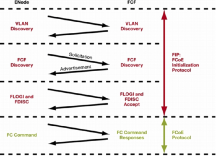
All the protocols are usually initiated by ENodes, although FCFs can generate unsolicited FIP advertisements. Note that the FIP frames at the top and the FCoE frames at the bottom of the figure above use different EtherTypes and encapsulations. Note that ENodes use different source MAC addresses for FIP and FCoE encapsulation. FIP packets are built using a globally unique MAC address assigned to the CNA at manufacturing (called the ENode MAC address). FCoE packets are encapsulated using a locally unique MAC address (that is, unique only within the boundaries of the local Ethernet subnet) dynamically assigned to the ENode by the FCF as part of the FIP virtual link establishment process (a fabric-provided MAC address [FPMA]). Figure FPMA
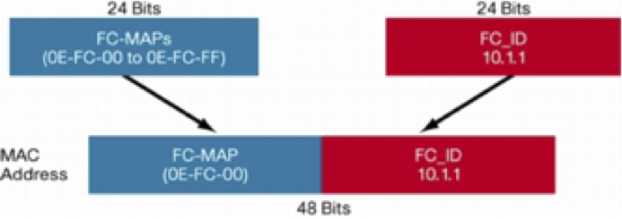
FPMAs use the 24-bit-wide Fibre Channel ID (FC_ID) assigned to the CNA during the FIP FLOGI and FDISC exchange, and therefore they cannot be available to the CNA before the fabric login has occurred. The FPMA is built by appending the FC_ID to a 24-bit quantity called the FCoE MAC address prefix (FC-MAP). FC-BB-5 defined a range of 256 FC-MAPs to facilitate FCoE deployments. Cisco has established very simple best practices (see "FCoE VLANs" earlier in this document) that make the manipulation of FC-MAPs unnecessary, and most users should find the default FC-MAP value 0E-FC-00 sufficient. The 256 different FC-MAPs make available to users up to 256 pools of locally unique MAC addresses. The pools are useful when the FC_IDs are not unique on an Ethernet VLAN; for instance, when different Fibre Channel fabrics or different VSANs are encapsulated in the same Ethernet VLAN, the ranges of FC_IDs assigned in each Fibre Channel fabric may overlap. Cisco strongly recommends that you never attempt to map multiple Fibre Channel fabrics onto the same Ethernet VLAN. Most users will not ever need to map multiple Fibre Channel fabrics onto the same physical Ethernet network, but if such a need arises, each Fibre Channel fabric should be encapsulated in a separate VLAN.
FIP VLAN Discovery
FIP VLAN discovery discovers the FCoE VLAN that will be used by all other FIP protocols as well as by the FCoE encapsulation for Fibre Channel payloads on the established virtual link. One of the goals of FC-BB-5 was to be as nonintrusive as possible on initiators and targets, and therefore FIP VLAN discovery occurs in the native VLAN used by the initiator or target to exchange Ethernet traffic. The FIP VLAN discovery protocol is the only FIP protocol running on the native VLAN; all other FIP protocols run on the discovered FCoE VLANs. The ENode sends a FIP VLAN discovery request to a multicast MAC address called All-FCF-MACs, which is a multicast MAC address to which all FCFs listen. All FCFs that can be reached in the native VLAN of the ENode are expected to respond on the same VLAN with a response that lists one or more FCoE VLANs that are available for the ENode's VN_Port login. This protocol has the sole purpose of allowing the ENode to discover all the available FCoE VLANs, and it does not cause the ENode to select an FCF. FIP VLAN discovery is an optional protocol in FC-BB-5. An ENode implementation can choose to offer only manual configuration for FCoE VLANs, and therefore choose not to perform FIP VLAN discovery. It is commonly assumed that such implementation will default to VLAN 1002 for its FCoE VLAN. The Cisco Nexus 5000 Series supports FIP VLAN discovery, and it will respond to any ENode that performs a query. The contents of the response depend on how the virtual FC interface is configured on the Cisco Nexus 5000 Series Switch, as discussed later in this document.
FIP FCF Discovery
FIP FCF discovery is the protocol used by ENodes to discover FCFs that can accept logins. FCFs periodically send FIP FCF discovery advertisement messages on each configured FCoE VLAN; these messages are destined for the multicast MAC address All-ENode-MACs, a multicast MAC address to which all ENodes listen. The FIP FCF discovery advertisement is used by the FCF to inform any potential ENode in the VLAN that FCF VF_Ports are available for virtual link establishment with ENodes' VN_Ports. The advertisement includes the MAC address of the FCF as well as other parameters useful for tuning the characteristics of the virtual link (FIP timeout values, FCF priority, etc.). Given the periodic nature of the advertisements, new ENodes joining the network will typically not want to wait to collect multicast FIP FCF discovery advertisements from all FCFs, and therefore FC-BB-5 allows ENodes to solicit unicast advertisements by sending a FIP FCF discovery solicitation to the All-FCF-MACs multicast MAC address. FCFs receiving the solicitation can generate a unicast FIP FCF discovery advertisement addressed to the requesting ENode. Upon collection of these advertisements, the ENode can make the final decision as to which FCF to contact for the establishment of a virtual link with its VN_Port.
FIP FLOGI and FDISC
After the ENode has discovered all FCFs and selected one for login, the last step is to inform the selected FCF of the intention to create a virtual link with its VF_Port. After this step, Fibre Channel payloads (encapsulated in FCoE frames) can start being exchanged on the new virtual link just established. On any native Fibre Channel link between an N_Port and an F_Port, the first protocol exchange performed as part of activating the data-link layer is the fabric login, or FLOGI, which results in the assignment of an FC_ID to the N_Port. In designing FIP, the T11 committee decided to merge the logical step of FCF selection by an ENode in FIP with the native Fibre Channel fabric login exchange. The result of this optimization is a single FIP exchange that serves both purposes of FCF selection, as well as fabric login and FC_ID allocation. This optimization is not only convenient; it is a requirement for obtaining an appropriate FPMA for the ENode to use in the subsequent FCoE encapsulated frames.
FIP FLOGI and FDISC are unicast frames almost identical to the native Fibre Channel FLOGI and FDISC frames they replace. The VN_Port sends an FLOGI or an FDISC request, followed by the corresponding FLOGI or FDISC accept payload from the FCF. Completion of this exchange terminates the FIP virtual link establishment phase.