
Lab 7
Lab 7: Overlay Transport Virtualization
Overlay Transport Virtualization Overview
OTV introduces the concept of "MAC routing," which means a control plane protocol is used to exchange MAC reachability information between network devices providing LAN extension functionality. This is a significant shift from Layer 2 switching that traditionally leverages data plane learning, and it is justified by the need to limit flooding of Layer 2 traffic across the transport infrastructure. As emphasized throughout this document, Layer 2 communications between sites resembles routing more than switching. If the destination MAC address information is unknown, then traffic is dropped (not flooded), preventing waste of precious bandwidth across the WAN.
OTV also introduces the concept of dynamic encapsulation for Layer 2 flows that need to be sent to remote locations. Each Ethernet frame is individually encapsulated into an IP packet and delivered across the transport network. This eliminates the need to establish virtual circuits, called Pseudowires, between the data center locations. Immediate advantages include improved flexibility when adding or removing sites to the overlay, more optimal bandwidth utilization across the WAN (specifically when the transport infrastructure is multicast enabled), and independence from the transport characteristics (Layer 1, Layer 2 or Layer 3).
Finally, OTV provides a native built-in multi-homing capability with automatic detection, critical to increasing high availability of the overall solution. Two or more devices can be leveraged in each data center to provide LAN extension functionality without running the risk of creating an end-to-end loop that would jeopardize the overall stability of the design. This is achieved by leveraging the same control plane protocol used for the exchange of MAC address information, without the need of extending the Spanning-Tree Protocol (STP) across the overlay. The following sections detail the OTV technology and introduce alternative design options for deploying OTV within, and between, data centers.
OTV Terminology
Edge Device
The edge device performs OTV functions: it receives the Layer 2 traffic for all VLANs that need to be extended to remote locations and dynamically encapsulates the Ethernet frames into IP packets that are then sent across the transport infrastructure.
It is expected that at least two OTV edge devices are deployed at each data center site to improve the resiliency.
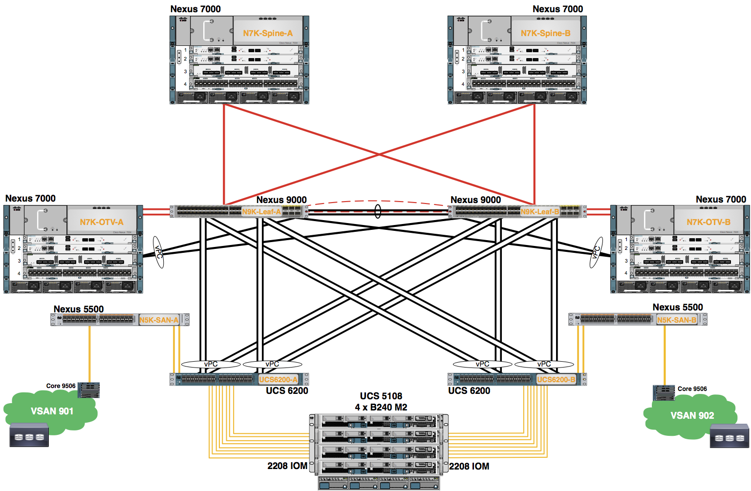
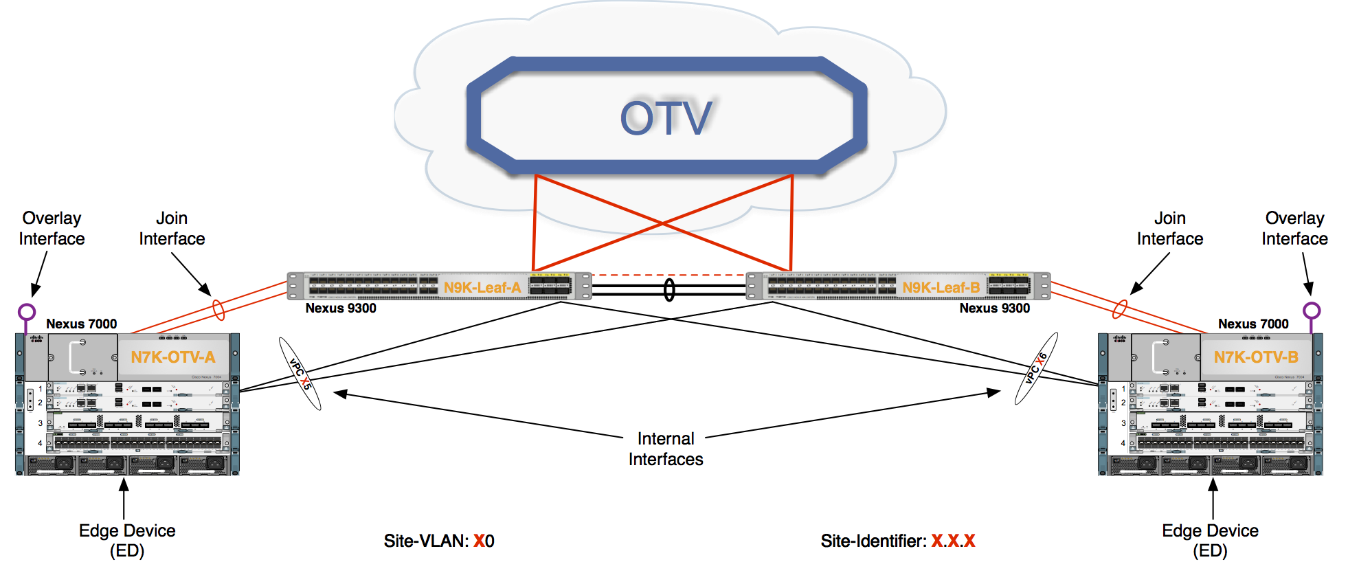
Finally, the OTV edge device can be positioned in different parts of the data center. The choice depends on the site network topology. The figure above shows edge device deployment at the aggregation layer.
Internal Interface
To perform OTV functionality, the edge device must receive the Layer 2 traffic for all VLANs that need to be extended to remote locations. The Layer 2 interfaces, where the Layer 2 traffic is usually received, are named internal interfaces. An M or F series line card may be used for the internal interface.
Internal interfaces are regular Layer 2 interfaces configured as access or trunk ports. Trunk configuration is typical given the need to concurrently extend more than one VLAN across the overlay. There is no need to apply OTV-specific configuration to these interfaces. Also, typical Layer 2 functions (like local switching, spanning-tree operation, data plane learning, and flooding) are performed on the internal interfaces. The figure above shows Layer 2 trunks that are considered internal interfaces which are usually deployed between the edge devices also.
Join Interface
The Join interface is used to source the OTV encapsulated traffic and send it to the Layer 3 domain of the data center network. An M series or F3 series line card can be used for the Join Interface.
The Join interface is a Layer 3 entity and with the current NX-OS release can only be defined as a physical interface (or subinterface) or as a logical one (i.e. Layer 3 port channel or Layer 3 port channel subinterface). A single Join interface can be defined and associated with a given OTV overlay. Multiple overlays can also share the same Join interface.
The Join interface is used by the edge device for different purposes:
- "Join" the Overlay network and discover the other remote OTV edge devices
- Form OTV adjacencies with the other OTV edge devices belonging to the same VPN
- Send/receive MAC reachability information
- Send/receive unicast and multicast traffic
Overlay Interface
The Overlay interface is a logical multi-access and multicast-capable interface that must be explicitly defined by the user and where the entire OTV configuration is applied.
Every time the OTV edge device receives a Layer 2 frame destined for a remote data center site, the frame is logically forwarded to the Overlay interface. This instructs the edge device to perform the dynamic OTV encapsulation on the Layer 2 packet and send it to the Join interface toward the routed domain.
Control Plane Considerations
As mentioned, one fundamental principle on which OTV operates is the use of a control protocol running between the OTV edge devices to advertise MAC address reachability information instead of using data plane learning. However, before MAC reachability information can be exchanged, all OTV edge devices must become "adjacent" to each other from an OTV perspective. This can be achieved in two ways, depending on the nature of the transport network interconnecting the various sites:
- If the transport is multicast enabled, a specific multicast group can be used to exchange the control protocol messages between the OTV edge devices.
- If the transport is not multicast enabled, an alternative deployment model is available starting from NX-OS release 5.2(1), where one (or more) OTV edge device can be configured as an "Adjacency Server" to which all other edge devices register and communicates to them the list of devices belonging to a given overlay.
Multicast Enabled Transport Infrastructure
Assuming the transport is multicast enabled, all OTV edge devices can be configured to join a specific ASM (Any Source Multicast) group where they simultaneously play the role of receiver and source. If the transport is owned by a Service Provider, the Enterprise will have to negotiate the use of this ASM group with the SP. The following figure shows the overall sequence of steps leading to the discovery of all OTV edge devices belonging to the same overlay.
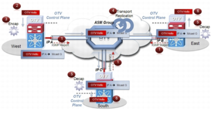
Step 1 Each OTV edge device sends an IGMP report to join the specific ASM group used to carry control protocol exchanges (group G in this example). The edge devices join the group as hosts, leveraging the Join interface. This happens without enabling PIM on this interface. The only requirement is to specify the ASM group to be used and associate it with a given Overlay interface.
Step 2 The OTV control protocol running on the left OTV edge device generates Hello packets that need to be sent to all other OTV edge devices. This is required to communicate its existence and to trigger the establishment of control plane adjacencies.
Step 3 The OTV Hello messages need to be sent across the logical overlay to reach all OTV remote devices. For this to happen, the original frames must be OTV-encapsulated, adding an external IP header. The source IP address in the external header is set to the IP address of the Join interface of the edge device, whereas the destination is the multicast address of the ASM group dedicated to carry the control protocol. The resulting multicast frame is then sent to the Join interface toward the Layer 3 network domain.
Step 4 The multicast frames are carried across the transport and optimally replicated to reach all the OTV edge devices that joined that multicast group G.
Step 5 The receiving OTV edge devices decapsulate the packets.
Step 6 The Hellos are passed to the control protocol process.
The same process occurs in the opposite direction and the end result is the creation of OTV control protocol adjacencies between all edge devices. The use of the ASM group as a vehicle to transport the Hello messages allows the edge devices to discover each other as if they were deployed on a shared LAN segment. The LAN segment is basically implemented via the OTV overlay.
Two important considerations for OTV control protocol are as follows:
- This protocol runs as an "overlay" control plane between OTV edge devices which means there is no dependency with the routing protocol (IGP or BGP) used in the Layer 3 domain of the data center, or in the transport infrastructure.
- The OTV control plane is transparently enabled in the background after creating the OTV Overlay interface and does not require explicit configuration. Tuning parameters, like timers, for the OTV protocol is allowed, but this is expected to be more of a corner case than a common requirement.
Note The routing protocol used to implement the OTV control plane is IS-IS. It was selected because it is a standard-based protocol, originally designed with the capability of carrying MAC address information in the TLV. In the rest of this document, the control plane protocol will be generically called "OTV protocol".
From a security perspective, it is possible to leverage the IS-IS HMAC-MD5 authentication feature to add an HMAC-MD5 digest to each OTV control protocol message. The digest allows authentication at the IS-IS protocol level, which prevents unauthorized routing message from being injected into the network routing domain. At the same time, only authenticated devices will be allowed to successfully exchange OTV control protocol messages between them and hence to become part of the same Overlay network.
Once OTV edge devices have discovered each other, it is then possible to leverage the same mechanism to exchange MAC address reachability information.
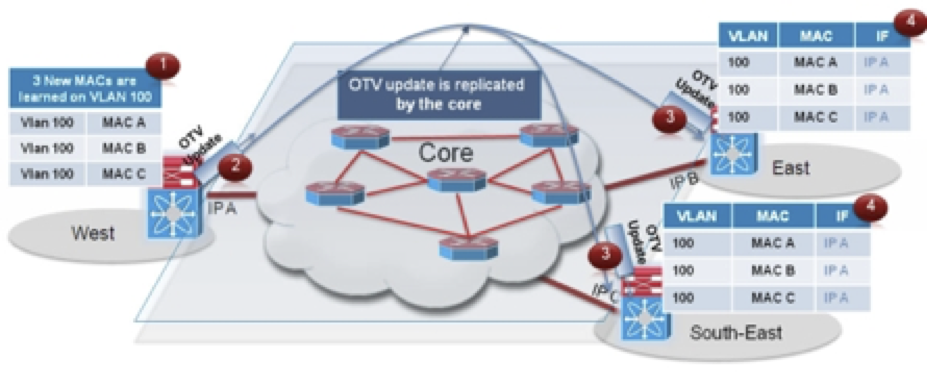
Step 1 The OTV edge device in the West data center site learns new MAC addresses (MAC A, B and C on VLAN 100) on its internal interface. This is done via traditional data plan learning.
Step 2 An OTV Update message is created containing information for MAC A, MAC B and MAC C. The message is OTV encapsulated and sent into the Layer 3 transport. Once again, the IP destination address of the packet in the outer header is the multicast group G used for control protocol exchanges.
Step 3 The OTV Update is optimally replicated in the transport and delivered to all remote edge devices which decapsulate it and hand it to the OTV control process.
Step 4 The MAC reachability information is imported in the MAC Address Tables (CAMs) of the edge devices. As noted in the previous figure, the only difference with a traditional CAM entry is that instead of having associated a physical interface, these entries refer the IP address of the Join interface of the originating edge device.
Note MAC table content shown in the previous figure is an abstraction used to explain OTV functionality.
The same control plane communication is also used to withdraw MAC reachability information. For example, if a specific network entity is disconnected from the network, or stops communicating, the corresponding MAC entry would eventually be removed from the CAM table of the OTV edge device. This occurs by default after 30 minutes on the OTV edge device. The removal of the MAC entry triggers an OTV protocol update so that all remote edge devices delete the same MAC entry from their respective tables.
VLAN Translation
You can extend VLANs over an OTV network in order to allow VLANs with the same VLAN ID to integrate seamlessly between local and remote sites. For example, when VLAN 1 on Site A is extended to Site B, VLAN 1 on Site A integrates seamlessly with VLAN 1 on Site B.
Beginning with Cisco NX-OS Release 6.2(2) and using an M series line card, you can map a VLAN on the local site to a VLAN with a different VLAN ID on the remote site. When you map two VLANs with different VLAN IDs across sites, they get mapped to a common VLAN called the transport VLAN. For example, when you map VLAN 1 on Site A to VLAN 2 on Site B, both VLANs are mapped to a transport VLAN. All traffic originating from VLAN 1 on Site A is translated as going from the transport VLAN. All traffic arriving at Site B from the transport VLAN is translated to VLAN 2.
OTV VLAN Translation with an F3 series line card is not supported. To achieve the same end result is to leverage VLAN Translation on a Trunk Port, i.e. VLAN Mapping using switchport vlan mapping vlan-id translated-vlan-id.
Traffic Depolarization
By default, OTV uses secondary IP addresses for route depolarization when using either an M series or F3 series line card. If you have two edge devices in an overlay network and each edge device is configured with two IP addresses, then four different IP header values are supported for forwarding unicast traffic between the edge devices. You must configure secondary IP addresses on the existing join interface to use route depolarization for this overlay network. Secondary IP addresses can be selected from the same subnet as the primary IP address. You do not need to configure multiple overlay networks between the same edge devices. Use the ip address ip-address mask secondary command to assign a secondary IP address.
On some overlay networks, secondary IP addresses on the join interface might be reserved for a different application. In this scenario, you must disable route depolarization for an entire system and to signal the lack of support for the corresponding tunnels to remote overlay members.
For route depolarization, OTV gleans its local source IP addresses from the local interface and the remote IP addresses through Intermediate-System-to-Intermediate-System (IS-IS). OTV creates multiple unicast tunnels and any one of these tunnels is used for output. Route depolarization is enabled only across multicast cores. If OTV uses a unicast core, tunnel depolarization with IP pools is not enabled. Through route depolarization, you can load balance traffic to these tunnels. Route depolarization programs forwarding to point to a group of all available tunnels and modifies the forwarding infrastructure to load balance based on the actual IP packet. This feature enables load balancing based on both source and destination MAC addresses, source and destination IP addresses, or on any other criteria available to the forwarding hardware.
By default, route depolarization is enabled. Use the otv depolarization disable command to disable the route depolarization feature. OTV displays the secondary IP addresses that are used by the overlay interfaces and adjacencies.
Encapsulation-Format
In Nexus 7000 NXOS 7.2(0)D1(1) with an F3 series line card and NXOS 7.3(0)DX(1) with an M3 series line card, support has been added to change the OTV encapsulation format from the default GRE encapsulation format to a UDP encapsulation format. This is to provide support for the OTV IETF standards track draft draft-hasmit-otv-03. Using UDP as the encapsulation format changes the overlay encapsulation into a Layer-2 Ethernet frame being encapsulated into IP/UDP. UDP encapsulation helps utilize more links in the core network as the UDP source port is varied automatically. OTV uses UDP port 8472 with every flow using a different UDP-source port. The header format aligns bit by bit with the header format used for the VXLAN header defined in IETF RFC 7348. OTV sites across a network should have the same encapsulation format configured.
Fast Convergence – Fast Failure Detection
AED Failure
If an AED has a local failure, it might become unable to forward traffic for all VLANs. The AED first ensures that it has disabled traffic forwarding for all VLANs. If the AED still has overlay or site reachability, the AED indicates this failure by bringing down its AED capability on either adjacency. If the AED does not have reachability or has shut down, other edge devices detect this failure by using a dual-adjacency timeout. In both cases, the preelected backup AEDs immediately assume authority for the respective VLANs after the AED failure has been determined.
Edge Device Failure
An edge device proactively informs neighbors about local failures. If an edge device shuts down before signaling its failure, the device's failure is determined by one or both of the following:
- Dual adjacency timeout—This method is used when both overlay and site adjacencies are lost. If only overlay adjacency is lost, the edge device is still deemed to be active. The VLAN AED status that was received previously from the edge device is maintained and is not deleted. Any AED transaction involving the edge device does not proceed until the edge device becomes reachable on the overlay or completely fails. If the edge device becomes completely isolated from the overlay, the edge device indicates a forwarding readiness failure on the site adjacency.
- Site edge device consensus—This method makes the failure detection more robust at the cost of extra latency and processing. All edge devices in the same site publish a list of edge devices to which they are adjacent, either on the overlay or on the site VLAN. When an edge device loses the overlay adjacency to another edge device, the first edge device immediately triggers a hello message with this list updated to exclude that edge device. If all edge devices in the site update the list, the edge device might have failed or is no longer reachable. All edge devices generate this list, but the list might not be used to determine the failure. At first, dual adjacency is used during AED election and transitions.
BFD over an SVI is used to detect neighbor failures within a site. Both site BFD and overlay route tracking must be configured for fast device failure detection within the site.
VLAN Failure
If an AED loses forwarding readiness for a VLAN, it generates a VLAN status update to disable both forwarding readiness and AED status bits. The backup AED can assume authority as soon as it receives the status update from the AED. The AED server-driven transition mechanism handles the failures of individual VLANs. The AED server processes the VLAN status update, runs the AED election, and generates a result that includes only the new AED value in its AED message. The backup AED then takes over as AED without waiting for any edge device's response.