Appendix C
Configure UCSM Server Ports
The purpose of this lab is to explore the configuration of Unified Ports as Server Ports on the UCS 6200 Series Fabric Interconnect using the UCSM Graphical User Interface (GUI).
Unified Ports on the 6200 Series Fabric Interconnect
Unified ports are ports on the 6200 series fabric interconnect that can be configured to carry either Ethernet or Fibre Channel traffic. These ports are not reserved. They cannot be used by a Cisco UCS domain until you configure them.
Configurable beacon LEDs indicate which unified ports are configured for the selected port mode.
- Port Modes
- Port Types
- Beacon LEDs for Unified Ports
- Guidelines for Configuring Unified Ports
- Cautions and Guidelines for Configuring Unified Uplink Ports and Unified Storage Ports
- Effect of Port Mode Changes on Data Traffic
- Configuring Port Modes for a 6248 Fabric Interconnect
- Configuring Port Modes for a 6296 Fabric Interconnect
- Configuring the Beacon LEDs for Unified Ports
Port Modes
The port mode determines whether a Unified Port on the Fabric Interconnect is configured to carry Ethernet or Fibre Channel traffic. The port mode is not automatically discovered by the Fabric Interconnect; it is configured in Cisco UCS Manager.
Changing the port mode results in the existing port configuration being deleted and replaced by a new logical port. Any objects associated with that port configuration, such as VLANs and VSANS, are removed. There is no restriction on the number of times the port mode can be changed for a Unified Port.
Port Types
The port type defines the type of traffic carried over a Unified Port connection.
On the older 6100 series Fabric Interconnect expansion module, the port modes were fixed – only certain ports could be used for specific applications (server, Ethernet Uplink, Fibre Channel Uplink). On the UCS 6200 series switch, used in this lab, all port are configurable for any of these port types.
By default, Unified Ports changed to Ethernet port mode are set to the Uplink Ethernet port type. Unified Ports changed to Fibre Channel port mode are set to the Fibre Channel Uplink Port type. Fibre Channel ports cannot be unconfigured.
Changing the port type does not require a reboot.
When the port mode is set to Ethernet, you can configure the following port types:
Server ports
Ethernet uplink ports
Ethernet port channel members
FCoE ports
Appliance ports
Appliance port channel members
SPAN destination ports
SPAN source ports
| For SPAN source ports, configure one of the port types and then configure the port as SPAN source. |
When the port mode is set to Fibre Channel, you can configure the following port types:
Fibre Channel uplink ports
Fibre Channel port channel members
Fibre Channel storage ports
FCoE Uplink ports
SPAN destination ports
SPAN source ports
References:
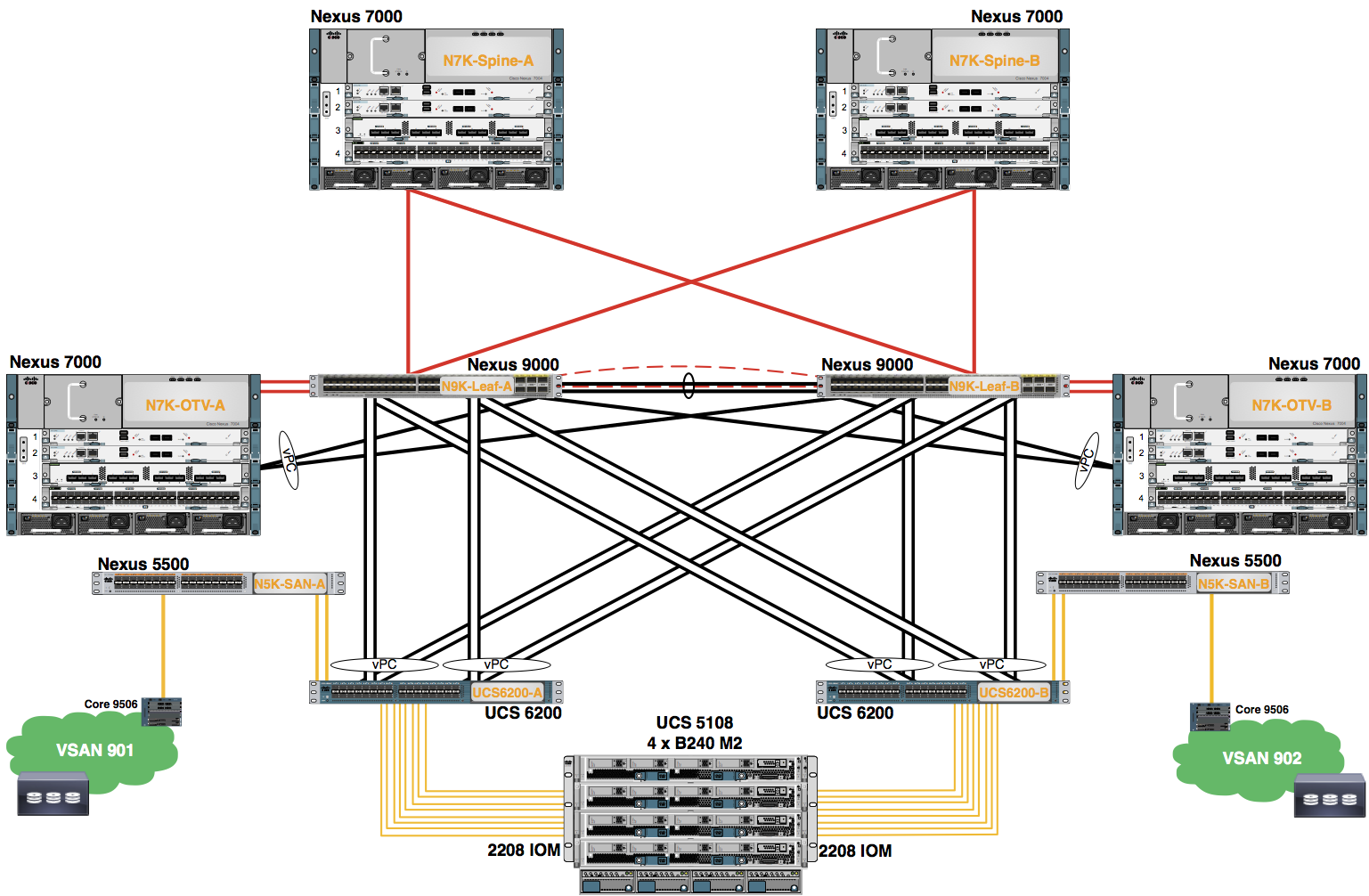
UCSM Initial Configuration GuideLAB: Enable the Server Ports Between the UCS 6200 Fabric Interconnects and the UCS 5108 Chassis
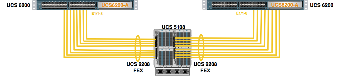
There are sixteen (16) connections between the UCS 6200s and the UCS 2208s. The UCS 2208 Fabric Extenders connect to Unified Ports 1/1 – 1/8 on each UCS 6200, Fabric Interconnect A (UCS6200-A) and Fabric Interconnect B (UCS6200-B), and are referenced in the following diagram.
Step 1. Configure the “Server Ports” on Fabric Interconnect 0
Expand “Fabric Interconnects” -> “Fabric Interconnect 0” -> “Fixed Module” -> “Ethernet Ports” by clicking the “+” sign next to each.
Select Ports 1 – 8 (click on Port 1, hold down the “Shift” key and click on Port 8).
Right-click on port 1.
Choose “Configure as Server Port”.
Click on “Yes” to configure the (8) objects as server port(s).
Click on “OK” to continue.
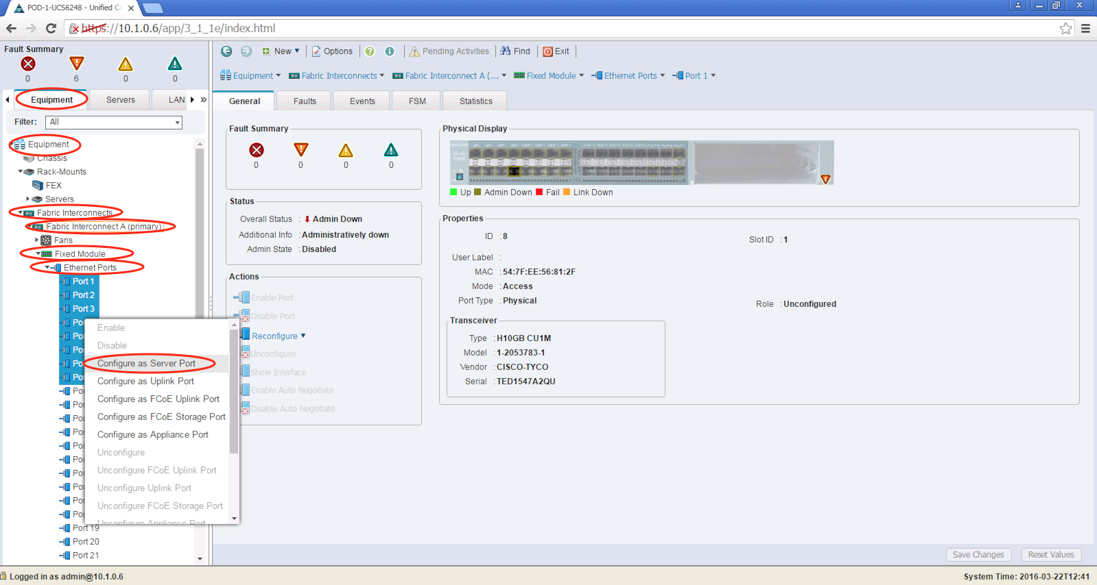
*If only one student is configuring the Pod, both Fabric Interconnects must be comfigured.
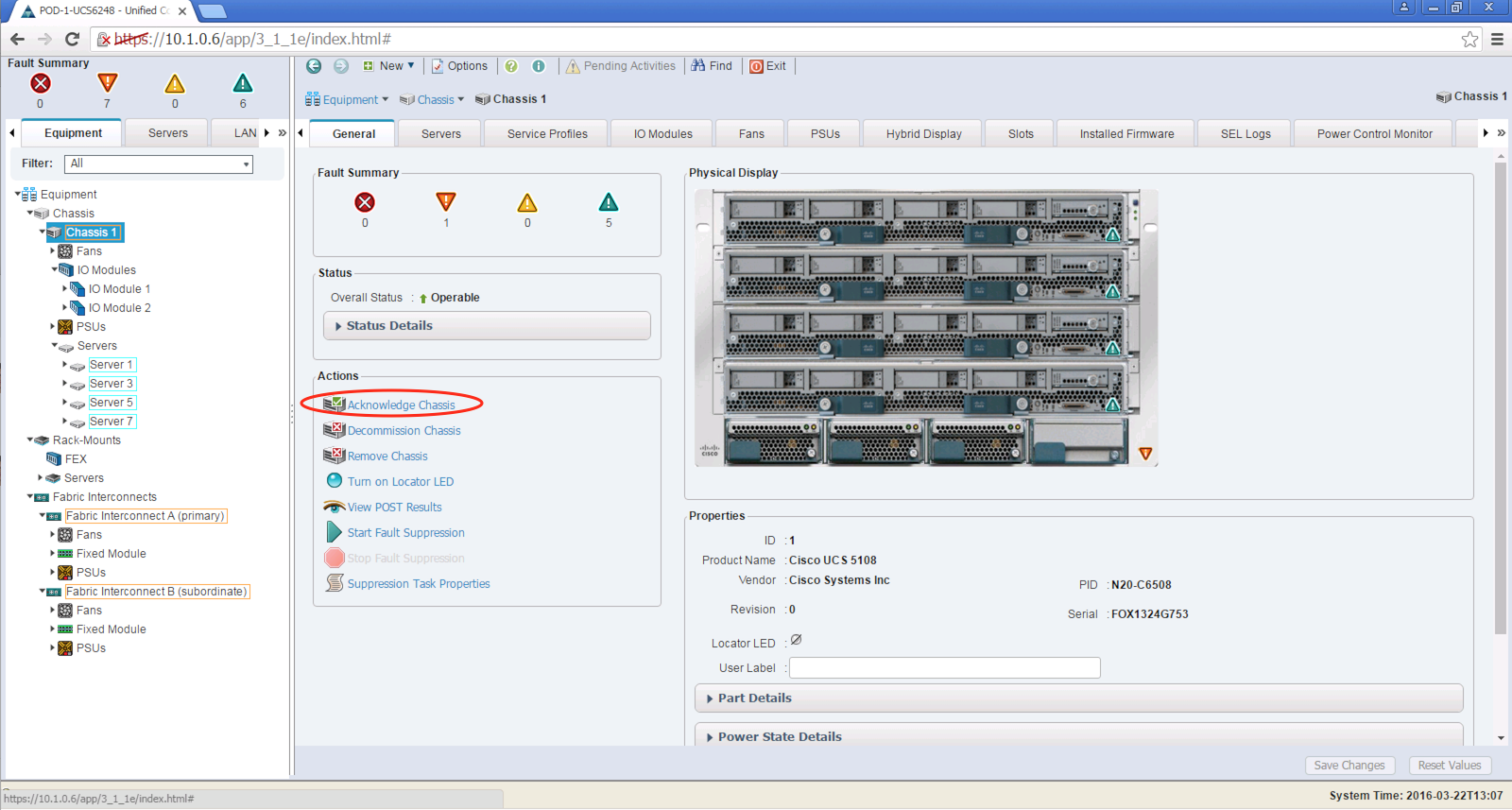
Step 2. Complete the Chassis discovery process by acknowledging the chassis
Expand “Equipment” -> “Chassis” by clicking the “+” sign next to each.
Select “Chassis 1”.
Select the action: “Acknowledge the Chassis”.
Click “Yes” to acknowledge Chassis 1.
Click “OK” to continue.
Only one student per Pod should complete this task. Coordinate with your lab partner to decide which student performs this task.