
Appendix F
Routing for OTV Transport and the VXLAN Underlay Transport
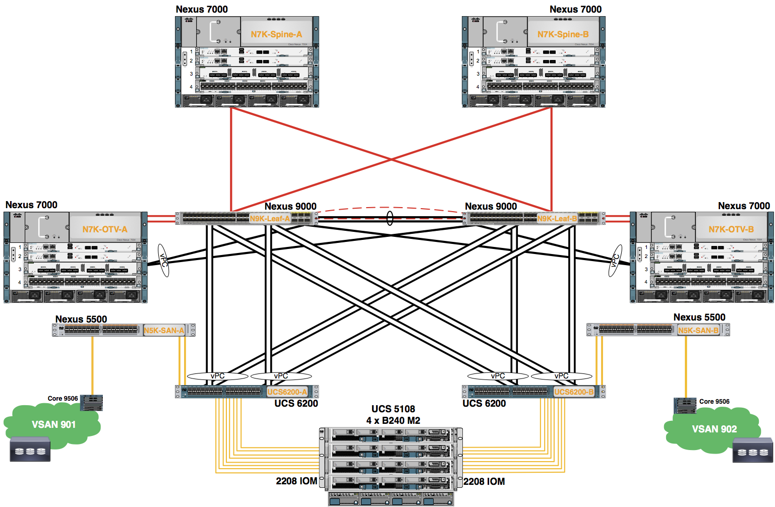
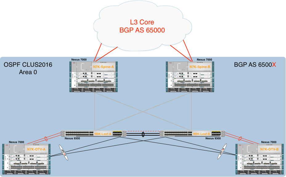
The purpose of this lab is to explore the configuration of the Layer 3 Routing configuration used for both normal IP traffic and the Underlay for the VXLAN Overlay.
Loopback Interfaces
A loopback interface is a virtual interface with a single endpoint that is always up. Any packet transmitted over a loopback interface is immediately received by this interface. Loopback interfaces emulate a physical interface. You can configure up to 1024 loopback interfaces per VDC, numbered 0 to 1023.
You can use loopback interfaces for performance analysis, testing, and local communications. Loopback interfaces can act as a termination address for routing protocol sessions. This loopback configuration allows routing protocol sessions to stay up even if some of the outbound interfaces are down.
Routed Interfaces
You can configure a port as a Layer 2 interface or a Layer 3 interface. A routed interface is a physical port that can route IP traffic to another device. A routed interface is a Layer 3 interface only and does not support Layer 2 protocols, such as the Spanning Tree Protocol (STP).
All Ethernet ports are routed interfaces by default. You can change this default behavior with the CLI setup script or through the system default switchport command.
You can assign an IP address to the port, enable routing, and assign routing protocol characteristics to this routed interface.
Beginning with Cisco Release 4.2(1), you can assign a static MAC address to a Layer 3 interface. By default, the MAC address for the Layer 3 interfaces is the MAC address of the VDC it is assigned to.
VLAN Interfaces or Switched Virtual Interfaces (SVIs)
A VLAN interface or switch virtual interfaces (SVI), is a virtual routed interface that connects a VLAN on the device to the Layer 3 router engine on the same device. Only one VLAN interface can be associated with a VLAN, but you need to configure a VLAN interface for a VLAN only when you want to route between VLANs or to provide IP host connectivity to the device through a virtual routing and forwarding (VRF) instance that is not the management VRF. When you enable VLAN interface creation, Cisco NX-OS creates a VLAN interface for the default VLAN (VLAN 1) to permit remote switch administration.
You must configure the VLAN network interface in the same VDC as the VLAN.
Note  You cannot delete the VLAN interface for VLAN 1.
Open Shortest Path First
OSPFv2 is an IETF link-state protocol for IPv4 networks. An OSPFv2 router sends a special message, called a hello packet, out each OSPF-enabled interface to discover other OSPFv2 neighbor routers. Once a neighbor is discovered, the two routers compare information in the Hello packet to determine if the routers have compatible configurations. The neighbor routers try to establish adjacency, which means that the routers synchronize their link-state databases to ensure that they have identical OSPFv2 routing information. Adjacent routers share link-state advertisements (LSAs) that include information about the operational state of each link, the cost of the link, and any other neighbor information. The routers then flood these received LSAs out every OSPF-enabled interface so that all OSPFv2 routers eventually have identical link-state databases. When all OSPFv2 routers have identical link-state databases, the network is converged. Each router then uses Dijkstra's Shortest Path First (SPF) algorithm to build its route table.
You can divide OSPFv2 networks into areas. Routers send most LSAs only within one area, which reduces the CPU and memory requirements for an OSPF-enabled router.
OSPFv2 supports IPv4, while OSPFv3 supports IPv6.
Border Gateway Protocol
Cisco NX-OS supports BGP version 4, which includes multiprotocol extensions that allow BGP to carry routing information for IP multicast routes and multiple Layer 3 protocol address families. BGP uses TCP as a reliable transport protocol to create TCP sessions with other BGP-enabled devices.
BGP uses a path-vector routing algorithm to exchange routing information between BGP-enabled networking devices or BGP speakers. Based on this information, each BGP speaker determines a path to reach a particular destination while detecting and avoiding paths with routing loops. The routing information includes the actual route prefix for a destination, the path of autonomous systems to the destination, and additional path attributes.
BGP selects a single path, by default, as the best path to a destination host or network. Each path carries well-known mandatory, well-known discretionary, and optional transitive attributes that are used in BGP best-path analysis. You can influence BGP path selection by altering some of these attributes by configuring BGP policies.
BGP also supports load balancing or equal-cost multipath (ECMP).
Bidirectional Forwarding Detection
BFD is a detection protocol designed to provide fast forwarding-path failure detection times for media types, encapsulations, topologies, and routing protocols. You can use BFD to detect forwarding path failures at a uniform rate, rather than the variable rates for different protocol hello mechanisms. BFD makes network profiling and planning easier and re-convergence time consistent and predictable.
BFD provides sub-second failure detection between two adjacent devices and can be less CPU-intensive than protocol hello messages because some of the BFD load can be distributed onto the data plane on supported modules.
On Layer 3 port-channels, BFD can operate on a per-link basis to establish BFD sessions for each link in the port-channel. This provides an aggregate result to the client protocols. BFD Per-link mode is currently NX-OS proprietary.
Step 1: Configure Loopback interfaces
Configure the loopback interfaces. These will be advertised within OSPF for multi-hop iBGP peerings.
Configure the following on Spine-0:
        #Config Block 1

        config
        interface Loopback0
        ip address 0.0.0.2/32
        no shut
        exit
        end
Configure the following on OTV-0:
        #Config Block 2

        config
        interface Loopback0
        ip address 0.0.0.8/32
        no shut
        exit
        end
Configure the following on Leaf-0:
        #Config Block 3

        config
        interface Loopback0
        ip address 0.0.0.6/32
        no shut
        exit
        end
Step 2: Configure Layer 3 Interfaces between Spine and OTV VDCs
Configure the N9K Leaf switch layer 3 interfaces to the OTV VDCs.
Configure the following on Leaf-0:
        #Config Block 4

        config
        interface ethernet 1/23-24
        channel-group 100 mode active
        no shutdown
        interface port-channel 100
        no switchport
        mtu 9216
        ip address 10.0.201.13/30
        no shutdown
        end
Configure the OTV VDC layer 3 interfaces to the N7K Spine VDCs.
Configure the following on OTV-0:
        #Config Block 5

        config
        feature lacp
        interface 4/41-42
        channel-group 100 mode active
        no shutdown
        interface port-channel 100
        no switchport
        mtu 9216
        ip address 10.0.201.14/30
        no shtudown
        end
Step 3: Configure the Layer 3 Interfaces between Spine and Leaf Devices
Configure a layer 3 interfaces from Spine devices to Leaf devices using the ports below:
| Pod # | Port to Leaf-A | Port to Leaf-B |
|---|---|---|
| 0 | Ethernet 3/9 | Ethernet 3/10 |
Configure the following on Spine-0:
        #Config Block 6

        config
        interface ethernet 3/9
        mtu 9216
        ip address 10.0.201.33/30
        no shutdown
        interface ethernet 3/10
        mtu 9216
        ip address 10.0.201.37/30
        no shutdown
        end
Configure the layer 3 interfaces from Leaf devices to Spine devices using the ports below:
| Pod # | Port to Spine-A | Port to Spine-B |
|---|---|---|
| 0 | Ethernet 1/51 | Ethernet 1/52 |
Configure the following on Leaf-0:
        #Config Block 7

        config
        inerface ethernet 1/51
        mtu 9216
        ip address 10.0.201.30/30
        no shutdown
        interface ethernet 1/52
        mtu 9216
        ip address 10.0.201.38/30
        no shutdown
        end
Step 4: Configure OSPF Routing with BFD
Enable the OSPF feature on the Spine VDCs, Leaf Switches, and OTV VDCs.
Configure the following on Spine-0, Leaf-0 and OTV-0:
        #Config Block 8

        config
        feature ospf
        end
Configure the OSPF process and enable it for authentication.
Configure the following on Spine-0:
        #Config Block 9

        config
        router ospf CLUS2016
        router-id 0.0.0.2
        area 0.0.0.0 authentication message-digest
        timers throttle spf 10 100 5000
        timers lsa-arrival 80
        timers throttle lsa 10 100 5000
        end
Configure the following on Leaf-0:
        #Config Block 10

        config
        router ospf CLUS2016
        router-id 0.0.0.6
        area 0.0.0.0 authentication message-digest
        timers throttle spf 10 100 5000
        timers lsa-arrival 80
        timers throttle lsa 10 100 5000
        end
Configure the following on OTV-0:
        #Config Block 11

        config
        router ospf CLUS2016
        router-id 0.0.0.8
        area 0.0.0.0 authentication message-digest
        timers throttle spf 10 100 5000
        timers lsa-arrival 80
        timers throttle lsa 10 100 5000
        end
Add the OSPF process to the loopback.
Configure the following on Spine-0, OTV-0 and Leaf-0:
        #Config Block 12

        config
        interface loopback0
        ip router ospf CLUS2016 area 0.0.0.0
        end
Add the OSPF process to the Layer 3 port-channels between the Leaf and OTV VDCs.
Configure the following on Leaf-0 and OTV-0:
        #Config Block 13

        config
        interface port-channel 100
        ip ospf authentication-key cisco
        ip ospf network point-to-point
        ip router ospf CLUS2016 area 0.0.0.0
        end
Add the OSPF process to the Layer 3 interfaces between the Spines and Leafs.
Configure the following on Spine-0:
        #Config Block 14

        config
        interface ethernet 3/9, ethernet 3/10
        ip ospf authentication-key cisco
        ip ospf network point-to-point
        ip router ospf CLUS2016 area 0.0.0.0
        end
Configure the following on Leaf-0:
        #Config Block 15

        config
        interface ethernet 1/51, ethernet 1/52
        ip ospf authentication-key cisco
        ip ospf network point-to-point
        ip router ospf CLUS2016 area 0.0.0.0
        end
Enable the BFD feature on your Spine VDCs, OTV VDCs, and Leafs.
Configure the following on Spine-0, OTV-0, and Leaf-0:
        #Config Block 16

        config
        feature bfd
        end
Configure BFD on the layer 3 links between Nexus 9300 Leaf and OTV VDCs.
Configure the following on Spine-0 and OTV-0:
        #Config Block 17

        config
        interface port-channel 100
        no ip redirects
        bfd interval 250 min_rx 250 multiplier 3
        no bfd echo
        bfd per-link
        ip ospf bfd
        end
Configure BFD on the layer 3 links between Nexus 7000 Spine and Nexus 9300 Leaf devices.
| Pod # | Port to Leaf-A | Port to Leaf-B |
|---|---|---|
| 0 | Ethernet 3/9 | Ethernet 3/10 |
| Pod # | Port to Spine-A | Port to Spine-B |
|---|---|---|
| 0 | Ethernet 1/51 | Ethernet 1/52 |
Configure the following on Spine-0:
        #Config Block 18

        config
        interface ethernet 3/9, ethernet 3/10
        no ip redirects
        bfd interval 250 min_rx 250 multiplier 3
        ip ospf bfd
        end
Configure the following on Leaf-0:
        #Config Block 19

        config
        interface ethernet 1/51, ethernet 1/52
        no ip redirects
        bfd interval 250 min_rx 250 multiplier 3
        ip ospf bfd
        end
Step 5: Configure Interfaces to the Core with IP address
Configure Layer 3 interfaces using the table below to Core-A and Core-B.
| Pod # | Port to Core-A | Port to Core-B |
|---|---|---|
| 0 | 4/33 | 4/34 |
Configure the following on Spine-0:
        #Config Block 20

        config
        interface ethernet 4/33
        no switchport
        mtu 9216
        ip address 10.100.0.6/30
        ip pim bfd-instance
        no shutdown
        interface ethernet 4/34
        no switchport
        mtu 9216
        ip address 10.200.0.6/30
        ip pim bfd-instance
        no shutdown
        end
Step 6: Configure BGP routing with BFD
Enable the BGP feature on both of the Nexus 7000 Spine devices.
Configure the following on Spine-0 and Leaf-0:
        #Config Block 21

        config
        feature bgp
        end
The BGP routing process itself is configured as follows:
Configure the following on Spine-0:
        #Config Block 22

        config
        router bgp 65000
        router-id 0.0.0.1
        address-family ipv4 unicast
        maximum-paths 2
        template peer Core-eBGP
        bfd
        remote-as 65000
        address-family ipv4 unicast
        neighbor 10.100.0.0/30
        inherit peer Core-eBGP
        neighbor 10.200.0.0/30
        inherit peer Core-eBGP
        end
Configure BFD on the core interfaces.
| Pod # | Port to Core-A | Port to Core-B |
|---|---|---|
| 0 | Ethernet 4/33 | Ethernet 4/34 |
Configure the following on Spine-0:
        #Config Block 23

        config
        interface Ethernet 4/33, Ethernet 4/34
        no ip redirects
        bfd interval 250 min_rx 250 multiplier 3
        end
Step 7: Configure Redistribution Between BGP and OSPF
Configure Redistribution between BGP and OSPF routing protocols. The local routes are redistributed into BGP and the Core Routes are redistributed into OSPF.
Configure the following on Spine-0:
        #Config Block 24

        config
        route-map BGP-TO-OSPF permit 10
        match tag 65000
        route-map OSPF-TO-BGP permit 10
        match route-type intra-area
        router ospf CLUS2016
        redistribute bgp 6500X route-map BGP-TO-OSPF
        router bgp 65000
        address-family ipv4 unicast
        redistribute ospf CLUS2016 route-map OSPF-TO-BGP
        end
Step 8: Verify OSPF, BGP, and BFD Configurations
Verify OSPF neighbors are established between the Nexus 7000 Spine and the Nexus 9300 Leaf devices by issuing “show ip ospf neighbors”.
Verify the following on Spine-0:
POD-0-Spine-0# show ip ospf neighbors
OSPF Process ID CLUS2016 VRF default
Total number of neighbors: 3
Neighbor ID Pri State Up Time Address Interface
0.0.0.5 1 FULL/ - 00:01:18 10.0.201.34 Eth3/?
0.0.0.6 1 FULL/ - 00:03:44 10.0.201.38 Eth3/?
POD-0-Spine-0#
Verify the following on Leaf-0:
POD-0-Leaf-A# show ip ospf neighbors
OSPF Process ID CLUS2016 VRF default
Total number of neighbors: 3
Neighbor ID Pri State Up Time Address Interface
0.0.0.5 1 FULL/ - 08:20:46 10.0.0.1 Vlan00
0.0.0.1 1 FULL/ - 00:01:18 10.0.201.29 Eth?/?
0.0.0.2 1 FULL/ - 00:03:44 10.0.201.37 Eth?/?
0.0.0.7 1 FULL/ - 00:04:58 10.0.201.14 Po100
POD-0-Leaf-0#
Verify the eBGP and iBGP neighbors have established by issuing “show ip bgp summary”.
Verify the following on Spine-0:
POD-0-Spine-0# show ip bgp summary
BGP summary information for VRF default, address family IPv4 Unicast
BGP router identifier 0.0.0.2, local AS number 65000
BGP table version is 133, IPv4 Unicast config peers 4, capable peers 4
45 network entries and 128 paths using 9688 bytes of memory
BGP attribute entries [10/1360], BGP AS path entries [4/36]
BGP community entries [0/0], BGP clusterlist entries [0/0]
Neighbor V AS MsgRcvd MsgSent TblVer InQ OutQ Up/Down State/PfxRcd
10.100.0.5 4 65000 15 8 133 0 0 00:03:54 39
10.200.0.5 4 65000 13 8 133 0 0 00:03:55 39
Verify the BFD neighbors are up by issuing “show bfd neighbors”.
You can also issue “show bfd neighbors application {ospf | pim | bgp | eigrp}” to see BFD neighborships established on a per-protocol basis.
Verify the following on Spine-0:
POD-0-Spine-0# show bfd neighbors
OurAddr NeighAddr LD/RD RH/RS Holdown(mult) State Int Vrf
10.100.0.6 10.100.0.5 1107296257/1157628215 Up 5823(3) Up Eth3/? default
10.200.0.6 10.200.0.5 1107296258/1157628220 Up 5823(3) Up Eth3/? default
10.0.201.37 10.0.201.38 1107296272/1090519041 Up 5959(3) Up Eth4/? default
10.0.201.33 10.0.201.34 1107296273/1090519041 Up 5155(3) Up Eth4/? default
POD-0-Spine-0#
Verify the following on Leaf-0:
POD-0-Leaf-0# show bfd neighbors
OurAddr NeighAddr LD/RD RH/RS Holdown(mult) State Int Vrf
10.0.201.13 10.0.201.14 1090519043/0 Up N/A(3) Up Po100 default
10.0.201.13 10.0.201.14 1090519044/1191182338 Up 504(3) Up Eth1/23 default
10.0.201.13 10.0.201.14 1090519045/1191182339 Up 504(3) Up Eth1/24 default
10.0.201.30 10.0.201.29 1090519041/1107296273 Up 5928(3) Up Eth?/ ? default
10.0.201.38 10.0.201.37 1090519042/1107296273 Up 4619(3) Up Eth?/? default
10.0.0.10 10.0.0.9 1090519043/1090519043 Up 595(3) Up Vlan00 default
POD-0-Leaf-0#