
Appendix E
Layer 2 Port-Channels and Spanning-Tree
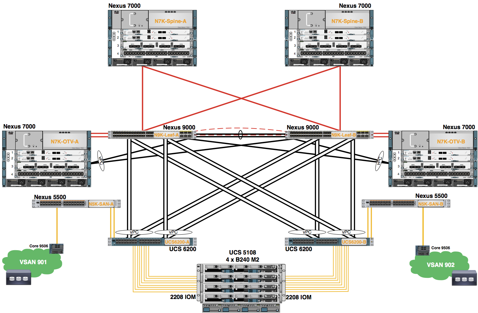
The purpose of this lab is to explore the configuration of the Layer 2 Port-Channels and Spanning-Tree in the Nexus 9300 series switches.
Step 1: Configure Layer 2 Port-Channels between the Nexus 9300s
Create a 20 Gbps Port-Channel between your Nexus 9300 switches.
(Note: This will be configured as the vPC peer-link in a later Lab.)
Configure the following on Leaf-0:
        #Config Block 1

        config
        feature lacp
        interface port-channel 00
        int e1/1-2
        channel-group 00 mode active
        no shut
        interface port-channel 00
        switchport
        no shut
        end
Step 2: Configure Spanning-Tree on the Nexus 9300 Leaf Switches
Configure Spanning-Tree on the Nexus 9300s such that these switches are the root bridge, not the OTV VDCs or any other Layer-2 switch.
Configure the following on Leaf-0:
        #Config Block 2

        config
        spanning-tree vlan 1, 10-12,20-22,000 priority 4096
        end
Step 3: Configure Layer 2 Port-Channels between N9K Leafs and OTV VDCs
Configure the port-channels to the OTV VDCs. These are port-channel 05 for OTV-A and port-channel 06 for OTV-B.
Configure the following on Leaf-0:
        #Config Block 3

        interface 1/26
        channel-group 06 mode active
        no shut
        interface port-channel 06
        switchport
        mtu 9216
        switchport mode trunk
        spanning-tree port type edge trunk
        no shut
        end
Layer 2 connectivity is required from each OTV VDC to the N9K Leafs. Port-Channels 05 and 06 have been preconfigured on OTV-A and OTV-B respectively. The VLANs must be configured on the OTV VDC for OTV to function properly.
Configure the following ports on your device(s).
| Pod # | Ports to AGG |
|---|---|
| 0 | E4/43-44 |
Configure the following on OTV-0:
        #Config Block 4

        config
        interface e4/43-44
        channel-group 06 mode active
        interface port-channe06
        switchport
        mtu 9216
        switchport mode trunk
        end
Step 4: Configure Layer 2 Port-Channels between N9Ks and FIs
The next step is to configure four 20 Gbps virtual Port-Channels from the Nexus 9300 switches to the UCS 6200 Fabric Interconnects.
Configure the following on Leaf-0:
        #Config Block 5

        config
        interface port-channel 01
        interface ethernet 1/9-10
        channel-group 01 mode active
        no shut
        interface port-channel01
        switchport
        swithcport mode trunk
        spanning-tree port type edge trunk
        no shut

        interface port-channel 02
        interface ethernet 1/11-12
        channel-group 02 mode active
        no shut
        interface port-channel02
        switchport
        swithcport mode trunk
        spanning-tree port type edge trunk
        no shut

        interface port-channel 03
        interface ethernet 1/11-12
        channel-group 03 mode active
        no shut
        interface port-channel03
        switchport
        swithcport mode trunk
        spanning-tree port type edge trunk
        no shut

        interface port-channel 04
        interface ethernet 1/13-14
        channel-group 04 mode active
        no shut
        interface port-channel04
        switchport
        swithcport mode trunk
        spanning-tree port type edge trunk
        no shut
        end
Step 5: Verify Layer 2 Port-Channels and Spanning-Tree
Verify the port-channel configurations:
Verify the following on Leaf-0:
        #Config Block 6

        show port-channel summary
Example Output From 'show port-channel summary'
POD-0-Leaf-0# show port-channel summary
Flags: D - Down P - Up in port-channel (members)
I - Individual H - Hot-standby (LACP only)
s - Suspended r - Module-removed
S - Switched R - Routed
U - Up (port-channel)
M - Not in use. Min-links not met
--------------------------------------------------------------------------------
Group Port- Type Protocol Member Ports
Channel
--------------------------------------------------------------------------------
00 Po 10(SU) Eth LACP Eth1/51(P) Eth1/52(P)
01 Po 01(SD) Eth LACP Eth1/9(D) Eth1/10(D) <<<< Down until UCS lab
02 Po 02(SD) Eth LACP Eth1/11(D) Eth1/12(D) <<<< Down until UCS lab
03 Po 03(SD) Eth LACP Eth1/13(D) Eth1/14(D) <<<< Down until UCS lab
04 Po 04(SD) Eth LACP Eth1/15(D) Eth1/16(D) <<<< Down until UCS lab
05 Po 05(SD) Eth LACP Eth1/25(P) <<<< May be in I-state until configured as vPC
06 Po 06(SD) Eth LACP Eth1/26(P) <<<< May be in I-state until configured as vPC
Verify the following on OTV-0:
        #Config Block 7

        show port-channel summary
Example Output From 'show port-channel summary'
POD-0-OTV-0# show port-channel summary
Flags: D - Down P - Up in port-channel (members)
I - Individual H - Hot-standby (LACP only)
s - Suspended r - Module-removed
S - Switched R - Routed
U - Up (port-channel)
M - Not in use. Min-links not met
--------------------------------------------------------------------------------
Group Port- Type Protocol Member Ports
Channel
--------------------------------------------------------------------------------
06 Po06(SU) Eth LACP Eth4/11(P) Eth4/12(P) <<<< May be in I-state until N9K vPC is configured
100 Po100(RU) Eth LACP Eth4/9(P) Eth4/10(P)
POD-0-OTV-A#