
Lab 2
Lab 2: Configure UCSM LAN
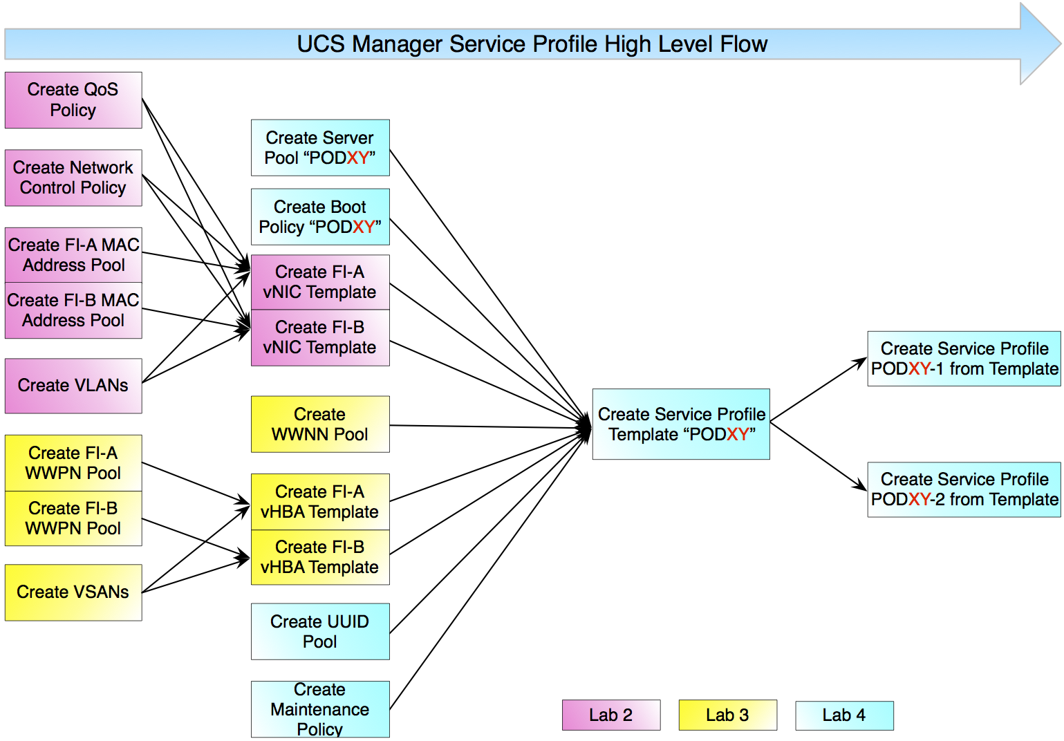
In this lab, we configure the network elements needed for the UCS 6200 Service Profile Templates in the new UCSM HTML5 web GUI. VLANs, Uplink Port-Channels, Layer 2 Networks, and MAC Address Pools are created. Some of these elements are applied to entities called vNIC Templates.
A high-level view, or flow-chart, of these steps are shown in the figure below.
Named VLANs
A named VLAN creates a connection to a specific external LAN. The VLAN isolates traffic to that external LAN, including broadcast traffic. The name that you assign to a VLAN ID adds a layer of abstraction that allows you to globally update all servers associated with service profiles that use the named VLAN. You do not need to reconfigure the servers individually to maintain communication with the external LAN.
A VLAN ID can:
- Be between 1 and 3967, 4048 and 4093
- You cannot create VLANs with IDs from 3968 to 4047. This range of VLAN IDs is reserved.
- Overlap with other VLAN IDs already defined on the system
- VLANs in the LAN cloud and FCoE VLANs in the SAN cloud must have different IDs. Using the same ID for a VLAN and an FCoE VLAN in a VSAN results in a critical fault and traffic disruption for all vNICs and uplink ports using that VLAN. Ethernet traffic is dropped on any VLAN ID that overlaps with an FCoE VLAN ID.
Network Control Policy
This policy configures the network control settings for the Cisco UCS domain, including the following:
- Whether the Cisco Discovery Protocol (CDP) is enabled or disabled
- How the virtual interface ( VIF) behaves if no uplink port is available in end-host mode
- The action that Cisco UCS Manager takes on the remote Ethernet interface, vEthernet interface, or vFibre Channel interface when the associated border port fails
- Whether the server can use different MAC addresses when sending packets to the fabric interconnect
- Whether MAC registration occurs on a per-VNIC basis or for all VLANs
Action on Uplink Fail
By default, the Action on Uplink Fail property in the network control policy is configured with a value of link-down. For adapters such as the Cisco UCS M81KR Virtual Interface Card, this default behavior directs Cisco UCS Manager to bring the vEthernet or vFibreChannel interface down if the associated border port fails. For adapters such as the Cisco UCS CNA M72KR-Q and the Cisco UCS CNA M72KR-E, the default behavior directs Cisco UCS Manager to bring the remote Ethernet interface down if the associated border port fails. Any vFibreChannel interfaces that are bound to the remote Ethernet interface are brought down as well.
Note: If your implementation includes the Cisco UCS CNA M72KR-Q or the Cisco UCS CNA M72KR-E adapter, we recommend that you configure the Action on Uplink Fail property with a value of “warning.” Please note that this configuration may result in a Ethernet teaming driver not being able to detect a link failure when the border port goes down.
MAC Registration Mode
Starting in release 2.0, MAC addresses are installed only on the native VLAN by default. In most implementations this maximizes the VLAN port count.
Note: If a trunking driver is being run on the host and the interface is in promiscuous mode, we recommend that you set the MAC Registration Mode to “All VLANs.”
MAC Pools
A MAC pool is a collection of network identities, or MAC addresses, that are unique in their Layer 2 environments and are available to be assigned to vNICs on a server. If you use MAC pools in Service Profiles (a logical view of a single blade server), you do not have to manually configure the MAC addresses to be used by the server associated with the Service Profile. In a system that implements multi-tenancy, you can use the organizational hierarchy to ensure that MAC pools can only be used by specific applications or business services. Cisco UCS uses the name resolution policy to assign MAC addresses from the pool.
Associate the MAC pool to a vNIC template to assign a MAC address to a server. Then, include the vNIC template in the Service Profile associated to a server.
A vNIC (Virtual Network Interface Controller) is a virtual interface providing Ethernet connectivity to a VLAN through a virtual interface on the 6200 Fabric Interconnect. The UCSM supports the creation of vNICs with different characteristics; these can be stored as templates, which are called vNIC Templates.
Quality of Service Policy
A quality of service (QoS) policy assigns a system class to the outgoing traffic for a vNIC or vHBA. The system class determines the quality of service and MTU for the traffic. For certain adapters, you can also specify additional controls on the outgoing traffic, such as burst and rate.
The QoS policy is associated to a vNIC template or a vHBA template. The Best Effort class is used by default.
vNIC Template
This policy defines how a vNIC on a server connects to the LAN. This policy must be included in a service profile for it to take effect. This policy requires that one or more of the following resources already exist in the system:
- Named VLAN
- MAC pool
- QoS policy
- LAN pin group
- Statistics threshold policy
Each of the Cisco UCS blade servers has a Cisco Virtual Interface Card (M81KR). The Virtual Interface Card allows you to create up to a 128 dynamic virtual interfaces and adapters. Since there are two UCS 6248s, we are going to create two total vNICS, one is bound to 6248-A, and one is bound to 6248-B. It does not matter how many vNICs are created, they all share a 10 Gbps pipe. The reasons for having different vNIC templates include the ability to bind them to different virtual switches, or being able to apply different MTU settings to different vNICs.