
Appendix D
Configure Disjoint Layer 2
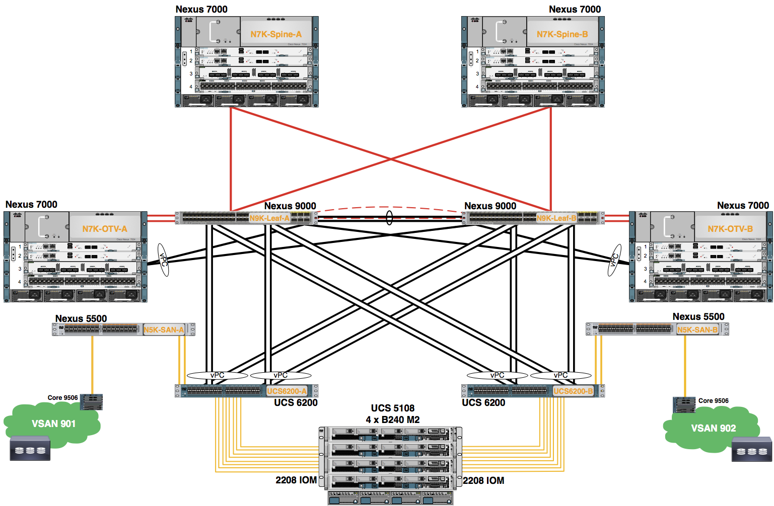
Disjoint layer-2 networks are required if you have two or more Ethernet “clouds” that never connect, but must be accessed by servers or virtual machines located in the same Cisco UCS domain. They are also required in a multi-tenant environment if servers or virtual machines for more than one customer are located in the same Cisco UCS domain and they need to access the L2 networks for both customers.
The configuration for disjoint L2 networks works on a principle of selective exclusion. Traffic for a VLAN that is designated as part of a disjoint network can only travel along an uplink Ethernet port or port channel that is specifically assigned to that VLAN, and is selectively excluded from all other uplink ports and port channels. Traffic for VLANs that are not specifically assigned to an uplink Ethernet port or port channel can still travel on all uplink ports or port channels, including those that carry traffic for the disjoint L2 networks.
The VLAN represents the upstream disjoint L2 network. Uplink interfaces are assigned to VLANs.
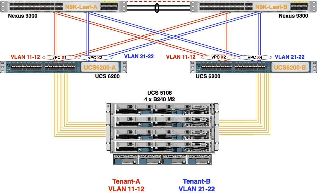
In this topology, VLAN traffic flows on different Port-Channels. This is useful in multi-tenancy designs.
- Configure disjoint Layer 2 networks.
- Click on the LAN tab.
- In the navigation pane click on the LAN node.
- In the LAN work pane, launch the LAN Uplinks Manager.
- Add your VLANs to the proper Port-Channels on Fabric A.
- In the LAN Uplinks Manager, click the VLANs tab.
- Click on the VLAN Manager tab (Located below the VLANs tab).
- Fabric A is the default Fabric in the diaglog box. In the Port Channels and Uplinks window, expand Fabric A using the +.
- In the VLANs and VLAN Group work pane, click the + to expand to view all the VLANs.
- Using the table above, select your Port-Channel on Fabric A.
- Using the VLANs portion of the table above, Shift+click both your VLANs in the VLANs and VLAN Group work pane.
- There are two scroll bars on the far right of the dialog windnow. Scroll down the first scroll bar.
- Scroll down the second scroll bar on the right of the dialog window.
- Click the Add to VLAN/VLAN Group button. Acknowledge the popup verification message with OK.
Again, a warning message appears when the VLANs are initially isolated to the specific uplink interface. Click the OK button to continue as this is verifying the pruning configuration of disjoint layer 2.
- Refer to the table in step 2, and add the VLANs to the Port-Channels on Fabric B.
- In the LAN Uplinks Manager, click the Fabric B tab.
- In the Port Channels and Uplinks window, expand Fabric B using the +.
- In the VLANs and VLAN Group work pane, click the + to expand to view all the VLANs.
- Using the table on the previous page, select your Port-Channel on Fabric B.
- Using the VLANs portion of the table above, Shift+click both your VLANs in the VLANs and VLAN Group work pane.
- There are two scroll bars on the far right of the dialog windnow. Scroll down the first scroll bar.
- Scroll down the second scroll bar on the right of the dialog window.
- Click the Add to VLAN/VLAN Group button. Acknowledge the popup verification message with OK.
- Click OK. Then, click OK to acknowledge the popup verification window.
- Re-open the LAN Uplinks Manager to view the VLANs allowed on each Port-Channel. (the process is outlined in step 1 above.) Click the VLANs tab. Click the VLAN Manager. Click the + button in the VLANs and VLAN Groups work pane.
- After completing this task for both your Fabric A and Fabric B Port-Channels, click the OK button to continue (again, you may need to scroll the far right two scroll bars). Then, click OK to acknowledge the popup verification window.