Lab 5
Lab 5: VXLAN MultiPod using NXAPI
In this lab we leverage the Virtual Extensible LAN (VXLAN) with the MP-BGP EVPN control plane configured in Lab 1 to configure VXLAN Multi-Pod.
In a VXLAN Multi-Pod design, multiple Data Center fabrics are treated as one large single administrative domain by extending the VXLAN Overlays between data centers whether that be rooms or buildings in the same geographic location or across different geographic locations. Other terminilogy that can be used to describe this solution is a VXLAN Stretched Fabric. It should be noted that this solution is not viable without the use of VXLAN EVPN (i.e. MP-BGP EVPN VXLAN) and Cisco enhanced features discussed below. Cisco strongly discourages and does NOT recommended the VXLAN Data Plane only VXLAN solution (VXLAN Flood & Learn or VXLAN F&L) as a Data Center Interconnect (DCI) solution. Traditionally, the different Pods connect via point-to-point fiber links when these different Pods exist within the same room or building and leverage dark fiber or DWDM circuits when they exist in different geographical locations.
VXLAN MultiPod Topology Options
Various deployment topologies can be considered for both methods of connectivity. One physical deployment topology to consider is the use of a pair of leaf switches that would act as Border Leafs or Transit Leafs to connect Pods directly via Layer 3. Another deployment topology to consider is to leverage the Spine switches in each Pod as Transit Spines or Inter-Pod Spines to connect Pods together via Layer 3. For the purposes of this lab, the second mentioned option will be deployed. In either design, VXLAN tunnels can be built between VTEPs in different Pods with these transit devices used in the forwarding path to route the encapsuslated VXLAN packets.
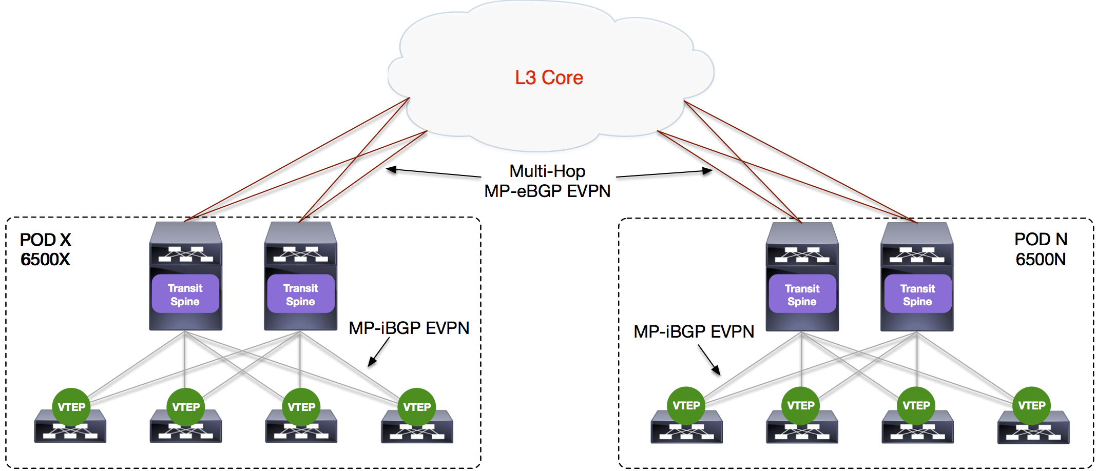
It is suggested to keep the Underlay control plane separate between Pods. For example, using two different OSPF Areas with the use of OPSF Area 0 between the Pods. Another example, and how the deployment was performed for this lab, is to use OSPF Area 0 in each Pod and eBGP between the Spines and Cores to separate the control planes. In Lab 6 it was established that the multicast RP used for BUM was placed in the Core in preparation for this lab as well as the optional OTV comparative lab. In realality, one could think of the Core as a Super Spine set. Another option for multicast RP deployment in VXLAN Multi-Pod would be to make each Spine an MSDP or PIM Anycast RP peer. To accomplish extending the VXLAN Overlay(s) Multi-Hop MP-eBGP EVPN will be used in this lab to peer between the Transit Spines in each Pod. Traditionally, since each Pod exists within a different BGP AS, the Route-Target values must be manually defined (import/export) for both VXLAN Bridging and VXLAN Routing. If the BGP AS did not change, then the ‘route-target auto’ configuration could be utilized to auto-generate this value as ASN:VNI. However, Cisco has developed a feature enhancement to ease the configuration between Pods using eBGP in the form of ‘rewrite-evpn-as’. This enhancement is currently available on the Nexus 7x00 series switches and will be utilized on your N7K Transit Spine during this lab.
A final consideration for VXLAN Multi-Pod is to take into consideration Layer 2 loops. The current VXLAN implementation does not contain a native mechanism to prevent Layer 2 loops, thus the use of features such as BPDU Guard or Storm Control along with care in using patch panels may be required.
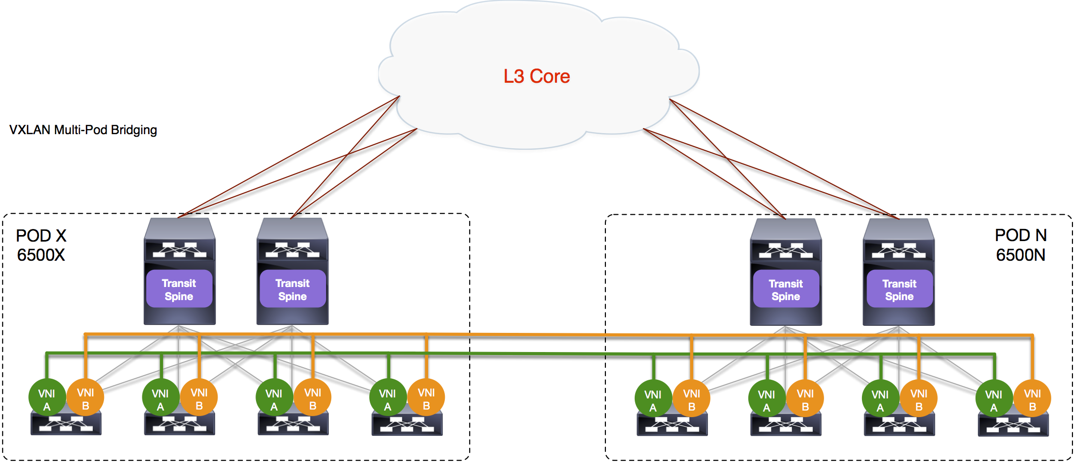
VXLAN MultiPod Bridging
Since the VXLAN Overlay has been extended between Pods over Layer 3, VLANs and their associated L2 Virtual Network Identifiers (VNIs) become logical Layer 2 segements extended across the Pods. This allows host connectivity wihthin the same VNI regardless of the Pod location. The association of these VLANs to VNIs and their respective mapping to the NVE tunnel interface on the was completed in Lab 1.
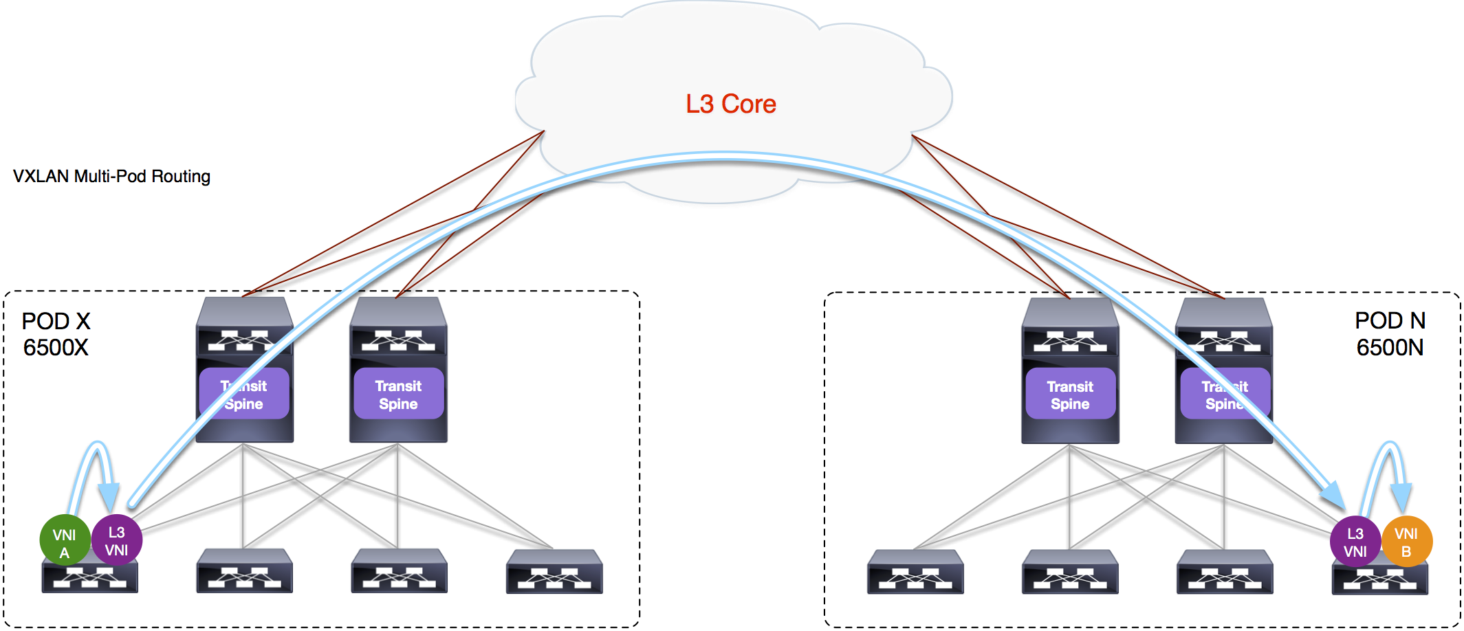
VXLAN MultiPod Routing
Additionally, multiple VXLAN Overlay(s) can be extended between Pods by use of VRFs with their respective Layer 3 VNI that were already used in the local data center or local Pod. For this solution to be efficient, it is requiremented that the distributed Layer 3 Anycast Gateway be present in all Pods. This allows for hosts and/or multi-tier applications to continue to use their respective local default gateway during a migration.