
Appendix H
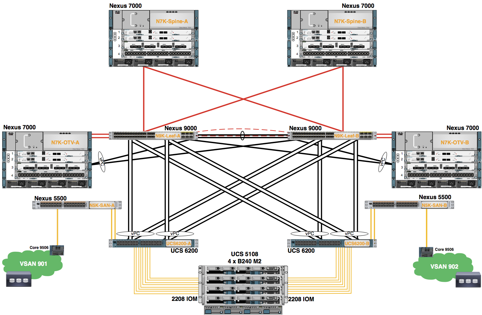
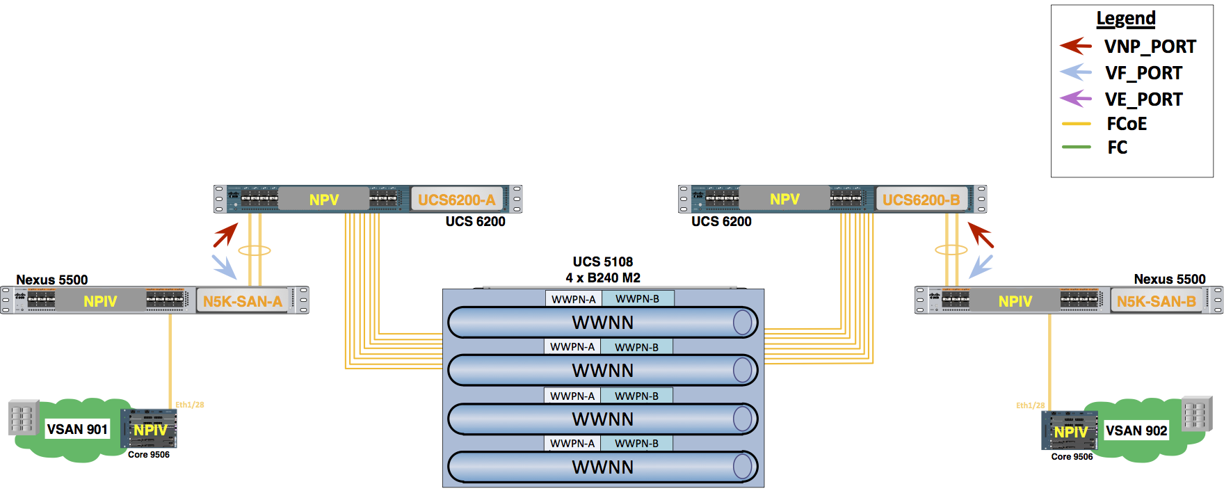
SAN FCoE and Zoning
The purpose of this lab is to explore the configuration of FCoE and SAN Zoning on the Nexus 5000s.
Step 1: Enable the FCoE and NPIV Features
- Enable the FCoE and NPIV features on your Nexus 5500s
Configure the following on N5K-0:
        #Config Block 1

        config
        feature fcoe
        feature npiv
        end
Step 2: Create a VSAN and FCoE VLANS on Nexus 5500s
The FCoE and NPIV features have already been configured.
Configure one VSAN on each of the Nexus 5500s.
Configure the following on N5K-0:
        #Config Block 2

        config
        vsan database
        vsan 902
        end
Configure one VLAN on each of the Nexus 5500s. Map the FCoE VLAN to the VSAN created in the previous step.
Configure the following on N5K-0:
        #Config Block 3

        config
        vlan 902
        fcoe vsan 902
        end
Step 3: Configure a Static Fibre Channel Domain
Define a domain ID on each Nexus 5500 (which is statically associated with the VSAN) and restart the fcdomain.
Configure the following on N5K-0:
        #Config Block 4

        config
        fcdomain domain 10 static vsan 902
        fcdomain restart vsan 902
        end

        show fcdomain vsan 902
Example Output From 'show fcdomain vsan 902'
Local switch run time information:
State: Stable
Local switch WWN: 23:86:54:7f:ee:5d:83:41
Running fabric name: 23:86:54:7f:ee:5d:83:41
Running priority: 128
Current domain ID: 0x0b(10)
Local switch configuration information:
State: Enabled
FCID persistence: Enabled
Auto-reconfiguration: Disabled
Contiguous-allocation: Disabled
Configured fabric name: 20:01:00:05:30:00:28:df
Optimize Mode: Disabled
Configured priority: 128
Configured domain ID: 0x0b(10) (static)
Principal switch run time information:
Running priority: 128
Step 4: Create SAN Zones and Zoneset on the Nexus 5500
TO SAVE TIME ON THIS STEP, A CUSTOM CONFIGURATION FILE HAS BEEN CREATED AND STAGED ON THE WINDOWS XP DESKTOP FOR EACH POD. OPEN THE FILE FOR YOUR POD NUMBER/STUDENT ID (LOCATED IN THE Cisco Live FOLDER ON YOUR DESKTOP), AND CUT AND PASTE THESE CONFIGURATIONS INTO THE NEXUS 5500s. BE CAREFUL TO USE THE CORRECT FILE FOR YOUR POD NUMBER AND STUDENT ID (A OR B).
Paste the zone information from the Pod-Specific file for your Pod
Configure the following on N5K-0:
        #Config Block 5

        config
        zone name POD0A-0-SP-1 vsan 902
        member pwwn 50:0a:09:81:8a:72:87:8d
        member pwwn 20:00:00:25:B5:00:0A:00

        zone name POD0A-0-SP-2 vsan 902
        member pwwn 50:0a:09:81:8a:72:87:8d
        member pwwn 20:00:00:25:B5:00:0A:01

        zone name POD0B-0-SP-1 vsan 902
        member pwwn 50:0a:09:81:8a:72:87:8d
        member pwwn 20:00:00:25:B5:00:0B:00

        zone name POD0B-0-SP-2 vsan 902
        member pwwn 50:0a:09:81:8a:72:87:8d
        member pwwn 20:00:00:25:B5:00:0B:01

        zoneset name POD0-0 vsan 902
        member POD0A-0-SP-1
        member POD0A-0-SP-2
        member POD0B-0-SP-1
        member POD0B-0-SP-2
        end
Activate the Zoneset
Configure the following on N5K-0:
        #Config Block 6

        config
        zoneset activate name POD0-0 vsan 902
        end
Step 5: Create vFC interface on Nexus 5500
Configure an Ethernet Port-Channel on the Nexus 5500s to trunk the correct VLAN. “switchport mode trunk” is required for the FCoE initialization Protocol (FIP).
Configure the following on N5K-0:
        #Config Block 7

        config
        interface port-channel 07
        switchport trunk allowed vlan 1,902
        end
Change the Port-channel load-balancing algorithm to optimize FCoE traffic.
Create a vFC on the Nexus 5500s for FCoE connectivity to UCS FIs.
Configure an Ethernet port to trunk the correct VLANs, “switchport mode trunk” is required for the FCoE initialization Protocol (FIP).
Create the core facing vFC interface using vFC X9 on both N5K-A and N5K-B.
Verify the zonesets have merged and that the Netapp storage array is logged into the fabric.
Save the device configurations.
Configure the following on N5K-0:
        #Config Block 8

        config
        port-channel load-balance ethernet source-dest-port
        end
Configure the following on N5K-0:
        #Config Block 9

        config
        interface port-channel 07
        no shut
        interface vfc 07
        bind  interface port-channel 07
        switchport mode F
        switchport trunk allowed vsan 902
        no shut
        end

Configure the following on N5K-0:
        #Config Block 10

        config
        interface e1/19
        switchport trunk allowed vlan 902
        no shut
        end
Configure the following on N5K-0:
        #Config Block 11

        config
        interface vfc 09
        bind  interface ethernet 1/19
        switchport trunk allowed vsan 902
        switchport mode E
        no shut
        end

        show interface vfc 09
Example Output From 'show interface vfc 09'
vfc09 is trunking
Bound interface is Ethernet1/19
Hardware is Ethernet
Port WWN is 20:12:54:7f:ee:5d:83:7f
Admin port mode is E, trunk mode is on
snmp link state traps are enabled
Port mode is TE
Port vsan is 1
Trunk vsans (admin allowed and active) (902)
Trunk vsans (up) (902)
Trunk vsans (isolated) ()
Trunk vsans (initializing) ()
1 minute input rate 53560 bits/sec, 6695 bytes/sec, 31 frames/sec
1 minute output rate 41368 bits/sec, 5171 bytes/sec, 31 frames/sec
2181 frames input, 359520 bytes
0 discards, 0 errors
2178 frames output, 276280 bytes
0 discards, 0 errors<\p>
Verify the following on N5K-0:
        #Config Block 12

        show zoneset active
Example Output From 'show zoneset active'
zoneset name CiscoLive-Fabric-0 vsan 902
zone name POD0A-0-SP-1 vsan 902
* fcid 0x950000 [pwwn 50:0a:09:81:8a:72:87:8d] [CiscoLive-C1-A]
pwwn 20:00:00:25:b5:00:0a:00
zone name POD0A-0-SP-2 vsan 902
* fcid 0x950000 [pwwn 50:0a:09:81:8a:72:87:8d] [CiscoLive-C1-A]
pwwn 20:00:00:25:b5:00:0a:01
zone name POD0B-0-SP-1 vsan 902
* fcid 0x950000 [pwwn 50:0a:09:81:8a:72:87:8d] [CiscoLive-C1-A]
pwwn 20:00:00:25:b5:00:0b:00
zone name POD0B-0-SP-2 vsan 902
* fcid 0x950000 [pwwn 50:0a:09:81:8a:72:87:8d] [CiscoLive-C1-A]
pwwn 20:00:00:25:b5:00:0b:01
        #Config Block 13

        wr